TRC66-86 *** 8
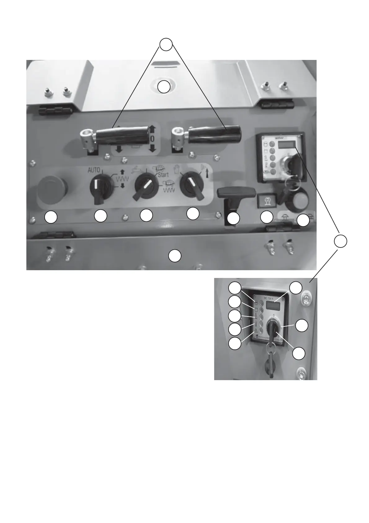
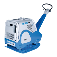
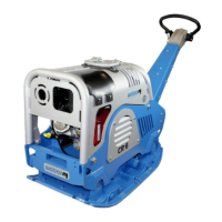
Figure 3
1.1.2 Controls and Indicators
7
4
5
1
3
6
8
9
1
10
2
1 Anti-vandalism flap
2 Emergency stop switch
3 Switch, vibration
4 Switch, working speed/start
5 Switch - manual operation/remote controlled operation
6 Hood unlocking lever
7 Pilot lamp, glow system
8 Engine speed adjustment (idling, full speed)
9 Electrical module
10 Drive levers, manual operation
11 Function control lamp
12 Alternator charge warning light
13 Low engine oil pressure indicator light
14 Temperature pilot lamp
15 Air filter service indicator light
16 Hourmeter
17 Ignition key
18 Ignition lock
18
17
16
15
14
13
12
11