Installation and operating instruction
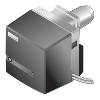
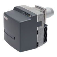
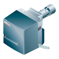
Oil burner WM-L20/2-A R (W-FM100/200)
13 Spares
83252902 1/2019-09 La
69-84
Pos. Description Order No.
2.01 Motor WM-D112/140-2/3K5 215 204 07 010
with motor contactor
2.02 Motor contactor B7, 230V 50Hz 702 818
2.03 Cable gland set 211 204 00 512
2.04 Motor WM-D112/140-2/3K5 215 204 07 020
for frequency converter mounted
2.05 Frequency converter configured 211 204 07 077
WM-D112/140-2/3K5 for W-FM 200
2.06 Shaft key 6 x 6 x 45 490 316
2.07 Fan wheel TS-S 268 x 104 S1 (50Hz) 211 204 08 011
– fan wheel puller (tool) 111 111 00 012
2.08 Washer 8.5 x 22 111 612 08 097
2.09 Screw M8 x 20 DIN 7991 with Precote 404 414
2.10 Inlet nozzle 285 x 209 x 43 (50Hz) 211 204 02 017
2.11 Air inlet mesh 211 204 02 222
– Screw M5 x 16 Duo Taptite 409 312
2.12 Air regulator complete 211 204 02 142
2.13 Air regulator 211 204 02 147
2.14 Air damper 211 204 02 077
– Screw M4 x 10 DIN 912 with TufLok 402 264
2.15 Actuator SQM45.291 B9 3Nm 651 501
– Cable entry cpl. with 2 W-FM plugs 217 605 12 052
2.16 Shaft key 3 x 3.7 DIN 6888 490 157
2.17 Air damper shaft with coupling 211 204 02 202
2.18 Air damper shaft with spring pin 211 204 02 212
2.19 Sleeve bearing set air regulator 211 104 02 502
2.20 Air regulator scale 211 314 02 177
2.21 Adjusting lever 211 104 02 047
2.22 Screw M5 x 12 with Precote 211 104 02 187
2.23 Ball joint rod 211 104 02 192
2.24 Screw M6 x 16 with TufLok 402 268
2.25 Screw M6 x 110 DIN 7500 409 364
2.26 Washer A6.4 DIN 125 430 400
2.27 Washer 5.1 x 11 x 0.6 430 015
 Loading...