The following explains the functions behind the individual menu items.
7.1. Run
The Sensor switches into display mode.
The set function of the pins is symbolically shown as follows:
AN
Analog output
A1 A2
Switching output A1 or A2
F
Error output
C
Contamination output
La
Laser shut-off
Teach input for A1 or A2
7.2. Pin Function
The Pin Function serves to determine the function of the pins E/A1 or E/A2. The pins can each take on different
functions.
E/A1 Configuration of pin E/A1
Switch
Error
Contaminate
Laser
Ext T A2
3 Back
7 Run
Switch: Switching output
Error: Error output
Contaminate: Contamination output
Laser: Input for switching the transmission light on and off
Ext T A2: Teach input for A2
E/A2 Configuration of pin E/A2
Switch
Error
Contaminate
Analog
Laser
Ext T A1
3 Back
7 Run
Switch: Switching output
Error: Error output
Contaminate: Contamination output
Analog: Analog output
Laser: Input for switching the transmission light on and off
Ext T A1: Teach input for A1
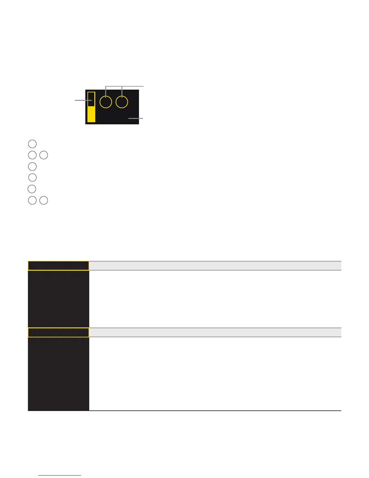
1500 mm
AN
A1
Bar graph display
of the current mea-
sured value relative
to the measuring
range
Selected pin function E/A1 (E/A2)
with respective status
Current measured value in mm