Dependence of Hysteresis and reproducibility on the Sampling Rate on white (90 % Remission)
OPT2011
Set Filter
Default setting for min.
hysteresis in mm
Reproducibility in mm
1 20 15
2 16 10
Default Settings 5 12 8
10 10 6
20 8 5
50 6 4
100 5 3
200 4 2
500 3 1
Power-on Drift
The following table provides information on the power-on drift during the warm-up phase.
Time in min 0 1 2 5 10
Power-on drift in mm ±7 ±5 ±4 ±2 ±0
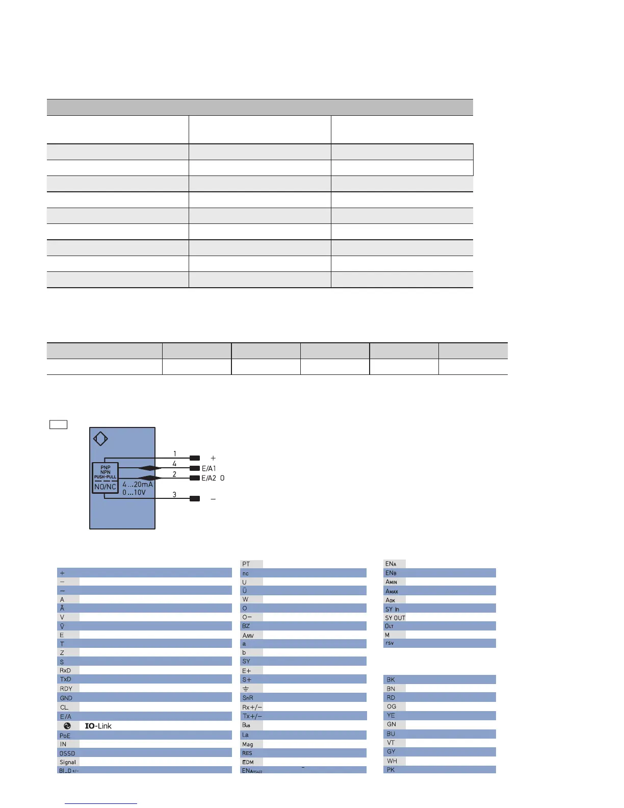
4.1. Connecting the Sensor
799
Legend
Wire Colors according to
DIN IEC 757
Platinum measuring resistor
not connected
Test Input
Test Input inverted
Trigger Input
Analog Output
Ground for the Analog Output
Block Discharge
Valve Output
Valve Control Output +
Valve Control Output 0 V
Synchronization
Receiver-Line
Emitter-Line
Grounding
Switching Distance Reduction
Ethernet Receive Path
Ethernet Send Path
Interfaces-Bus A(+)/B(–)
Emitted Light disengageable
Magnet activation
Input confirmation
Contactor Monitoring
Supply Voltage +
Supply Voltage 0 V
Supply Voltage (AC Voltage)
Switching Output (NO)
Switching Output (NC)
Contamination/Error Output (NO)
Contamination/Error Output (NC)
Input (analog or digital)
Teach Input
Time Delay (activation)
Shielding
Interface Receive Path
Interface Send Path
Ready
Ground
Clock
Output/Input programmable
Power over Ethernet
Safety Input
Safety Output
Signal Output