DC
CIRCUIT/BATTERY
DESCRIPTION
The
DC
Circuit
functions
to
start, operate and
stop
the
generator's engine.
The
circuit
is
best understood
by
reviewing
the
DC
Wiring
Diagram
and
Wiring
Schematic.
The engine's
DC
wiring
is
designed
with
three
simple
basic
circuits: start,
run,
and
stop.
The engine
has
a
12
volt
DC
electrical control circuit that
is
shown
on
the
Wiring
Diagrams.
Refer
to
these diagrams
when
troubleshooting
or
when
servicing
the
DC
electrical
system
on
the
engine.
A
CAUTION:
To
avoid
damage
to
the
battery
charging
circuit,
never
shut
off
the
engine
battery
switch
while
the
engine
is
running.
Shut
off
the
engine
battery
switch,
however,
to
avoid
electrical
shorts
when
working
on
the
engine's
electrical
circuit.
Specifications
The
minimum
recommended
capacity
of
the
dedicated battery
used
in
the engine's
12
volt
DC
control circuit
is
600-900
CCA.
Battery
Charging
Circuit
The engine supplies a continuous 6
amp
charge
from the
voltage regulator
to
the
engine's
battery.
This
charge
passes
thru
an
8
amp
fuse
(and
the
ships
battery
switch).
Testing
the
Circuit
If
the
battery
is
not charging, check
the
fuse.
To
test
the
circuit,
remove
the
fuse
and
test
with
a voltmeter between
the
fuse
holder connection
and
ground.
With
the
engine
running,
it
should
indicate 13.0-
13.1
volts.
If
only battery voltage
is
indicated, check the terminal connections
at
the
battery.
Battery
Maintenance
Review
the
manufacturer's recommendations
and
then
establish a systematic maintenance schedule
for
your
engine's starting batteries
and
house batteries.
• Check
the
electrolyte level and specific gravity
with
a
hydrometer.
•
Use
only
distilled water
to
bring electrolytes
to
a proper
level.
• 'Make certain that battery cable connections
are
clean
and
tight
to
the
battery posts (and
to
your
engine).
•
Keep
your
batteries clean
and
free
of
corrosion.
NOTE:
Ensure
that
the
B+
battery cable connected
to
the
remote
mounted starter solenoid
is
properly supported
to
prevent unwanted
stress
on
the
solenoid.
SHORE
POWER
TRANSFER
SWITCH
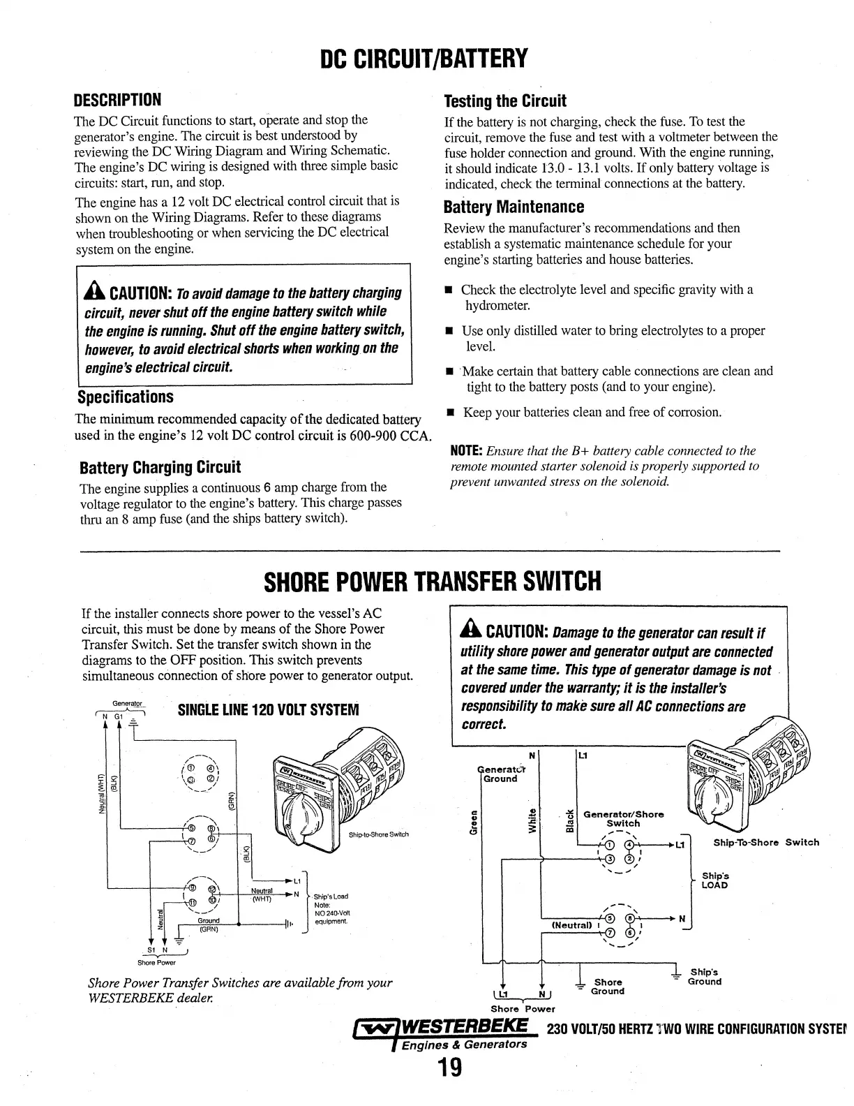
If
the
installer connects shore power
to
the
vessel's
AC
circuit,
this
must be
done
by
means
of
the
Shore Power
Transfer
Switch. Set
the
transfer switch shown
in
the
diagrams
to
the
OFF position. This switch prevents
simultaneous connection of shore power
to
generator
output.
SINGLE
LINE
120
VOLT
SYSTEM
I :
·(WH1')
N ·sh;p'sload
1
Note:
_,--
.....
,
~L1}
]!
--"
N0240.Volt
l
~c:arountl:;r.N;::-)
----tit•
equipment.
.
~
Shore
Power
Shore
Power Transfer Switches are available from your
WESTERBEKE
dealer.
A
CAUTION:
Damage
to
the
generator
can
result
if
utility
shore
power
and
generator
output
are
connected
at
the
same
time.
This
type
of
generator
damage
is
not
.
covered
under
the
warranty;
it
is
the
installer's
responsibility
to
make
sure
all
AC
connections
are
co"ect.
enerato:lt
Ground
N
I
L1
N J
I
Shore
Power
L1
Shore
-
Ground
Shlp·To·Shore
Switch
Ship's
LOAD
Shlp"s
Ground
....,;:~~.::;::-.:..:;~:;;,;;;;;;~~
230
VOLT/50
HERTZ
lWO
WIRE
CONFIGURATION
SYSTEr
Engine$ & Generator•
19