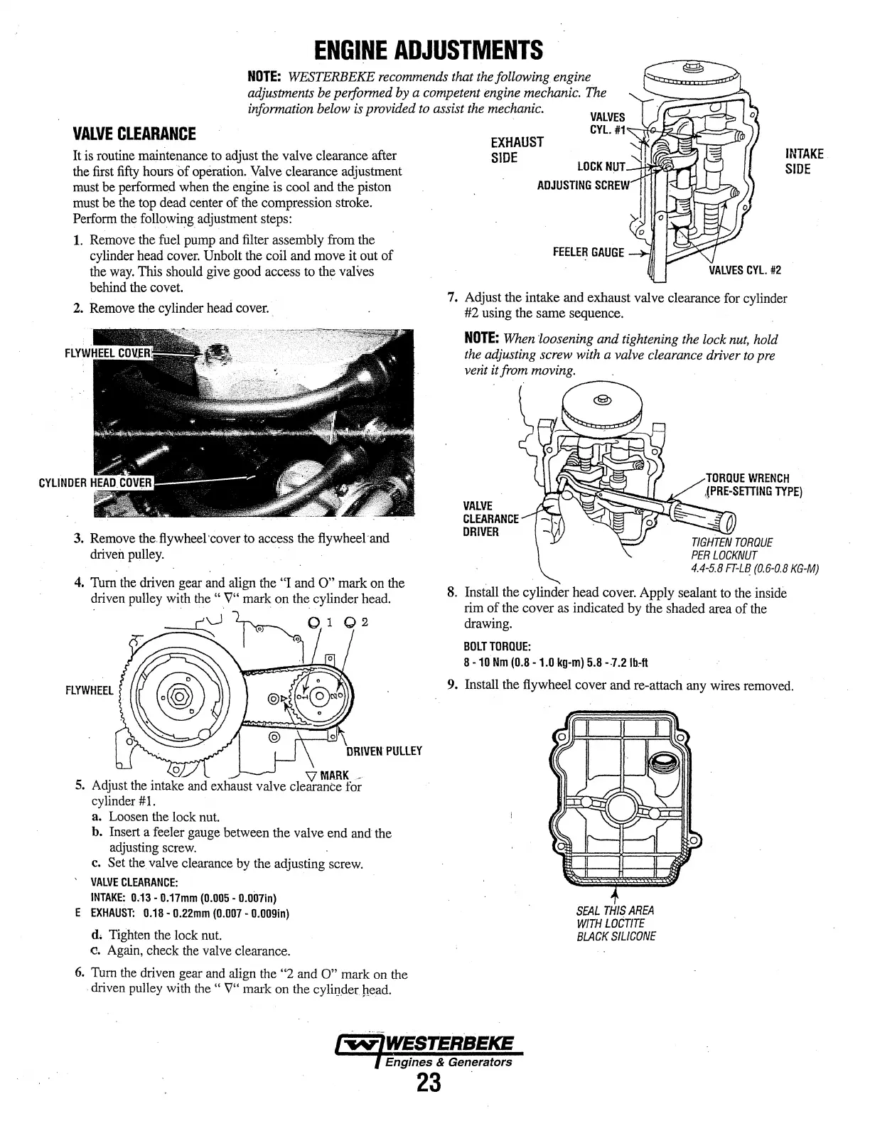
ENGINE
ADJUSTMENTS
NOTE:
WESTERBEKE
recommends
that
the
following engine
adjustments
be
performed by a competent
engine
mechanic.
the
information
below
is provided
to
assist
the
mechanic.
VALVES
VALVE
CLEARANCE
It
is
routine
maintenance
to
adjust the valve clearance after
the
first
fifty
hours
of
operation.
Valve
clearance adjustment
must
be
performed
when
the
engine is cool
and
the
piston
must
be
the
top
dead center of
the
compression stroke.
Perform
the
following_
adjustment
steps:
1.
Remove
the
fuel
pump
and
filter assembly
from
the
cylinder
head
cover.
Unbolt
the
coil and
move
it out of
the
way.
This
should
give
good access
to
the valves
behind
the
covet.
2.
Remove
the
cylinder
head
cover ..
3.
Remove
the.flywheei·coverto access the flywheei·and
driven
pulley.
· ·
FLYWHEEL
. .
0
~
VMAA~-
5.
Adjust
the
mtake
and
exhaust valve clearance for
cylinder
#I.
a.
Loosen
the
lock
nut.
b.
Insert
a feeler
gauge
between
the valve
end
and
the
adjusting
screw.
c.
Set
the
valve
clearance
by
the
adjusting
screw.
VALVE
CLEARANCE:
INTAKE:
0.13
•
0.17mm
(0.005
•
0.007in)
E
EXHAUST:
0.18
•
0.22mm
(0.007
•
0.009in)
d,
Tighten
the
lock
nut.
c.
Again,
check
the
valve
clearance.
6.
Tum
the
driven
gear
and
align
the
"2
and
0"
mark
on
the
·driven
pulley
with
the
"
'\7"
mark
on
the
cyliiJder
head.
EXHAUST
SIDE
CYL.
#1~~~~:=::=;'1ib
ADJUSTING
SCREW
FEELER
GAUGE
INTAKE
SIDE
7.
Adjust the intake and exhaust valve clearance
for
cylinder
#2 using
the
same sequence.
NOTE:
When
'loosening
and tightening
the
lock
nut,
hold
the
adjusting screw
with
a valve clearance driver
to
pre
vent it
from
moving.
VALVE
CLEARANCE
DRIVER
TIGHTEN
TORQUE
PER
LOCKNUT
4.4·5.8
FT-LB_
(0.6-0.8
KG·M)
8.
Install the cylinder head
cover.
Apply sealant
to
the
inside
rim
of the cover as indicated by
the
shaded
area
of
the
drawing.
BOLT
TORQUE:
8-10
Nm
(0.8
-1.0kg-m)
5.8
--7.21b"ft
9. Install the flywheel cover and re-attach any wires
removed.
SEAL
THIS
AREA
WITH
LOCTITE
BLACK
SILICONE
Engines & Generators
23