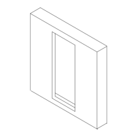
3-11
ALARM COM
ALARM NO
ALARM NC
6
7
8
TB1
Figure 3-13
Alarm Relay Contacts
System Trouble Status Output Contact Wiring
The location of the Trouble Status output connections are shown in Figure 3-10 Section 2 on Page 3-
10. A magnified view of this area on the Mother Board is shown in Figure 3-12 on Page 3-11.
• Wire gauge selection of the system Trouble Status output contact wiring should involve
consideration of all factors including, wire length, maximum current capacity, and maximum
voltage drop allowable.
• The system Trouble Status output contact is Form C, rated for 0.5 amps at 24 VDC,
resistive load.
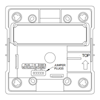
• For a detail of the system Trouble Status output contact Terminal connections (shown and
marked in the trouble condition), see Figure 3-14.
TRB COM
TRB NO
TRB NC
3
4
5
TB1
Figure 3-14
Trouble Status Relay Contacts
Trouble Audible Output Wiring
• Wire gauge selection of the System Trouble Output Contact wiring involves consideration
of all factors including wire loop length, maximum current capacity, and maximum voltage
drop allowable.
• The Trouble Audible output is rated for 24VDC, 0.1 amps maximum. The output is
unsupervised.
• Wiring diagram for the unsupervised Trouble Audible output connection – Figure 3-15
 Loading...