7-3
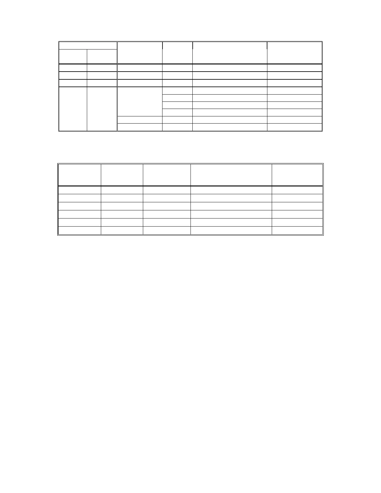
Table 7-1
Module Trouble Procedure Cross Reference
Mother Board (SCMB)
NORMAL
LED
TROUBLE
LED
Module
LED
Trouble Description
Troubleshooting
Procedure
ON OFF Normal
OFF OFF Power Loss A
ON ON Faulty Mother Board B
OFF ON STROBE Visual Notification Circuit C
SAA/SALL AUDIO Audio Output Wiring D
PWR 24VDC Speaker Power E
AMP SAA/SALL Module F
RMS-2 TROUBLE Remote Microphone Trouble G
MDX-2 TROUBLE Digital Voice Module Trouble See Table 7-2
Table 7-2
MDX-2 Trouble Procedure Cross Reference
DV Module
System Normal
LED (Green)
DV Module
System Trouble
LED (Amber)
DV Module
Trouble Indicator
LED (Amber)
What it Means
Troubleshooting
Procedure
On Off Off Normal ----
Off Off Off Power Loss H
Off On Off DV Module Inoperative I
Off On Steady-On DV Module Inoperative J
Off On 2 Blink Pattern Message Memory Error K
Off On 4 Blink Pattern Output Channel Error L
Figure 7-2 on Page 7-4 is the basic troubleshooting flowchart describing the troubleshooting procedure in
a graphic manner. The following flowchart contains the same information as described in Tables 7-1 and
7-2.
 Loading...