13.1 Schematic diagrams - general
13.1.1 Engine control diagram
The engine control diagram shows data about the control items of the engine and its systems.
In the sub-sections that follow you find general data about the engine control diagram.
13.1.1.1 Area codes in the engine control diagram
The area codes in the engine control diagram are as follows:
•
A - Control air supply unit
•
B - Fuel supply
•
D - Servo oil supply
•
E - Valve unit for start
•
K - Local control panel.
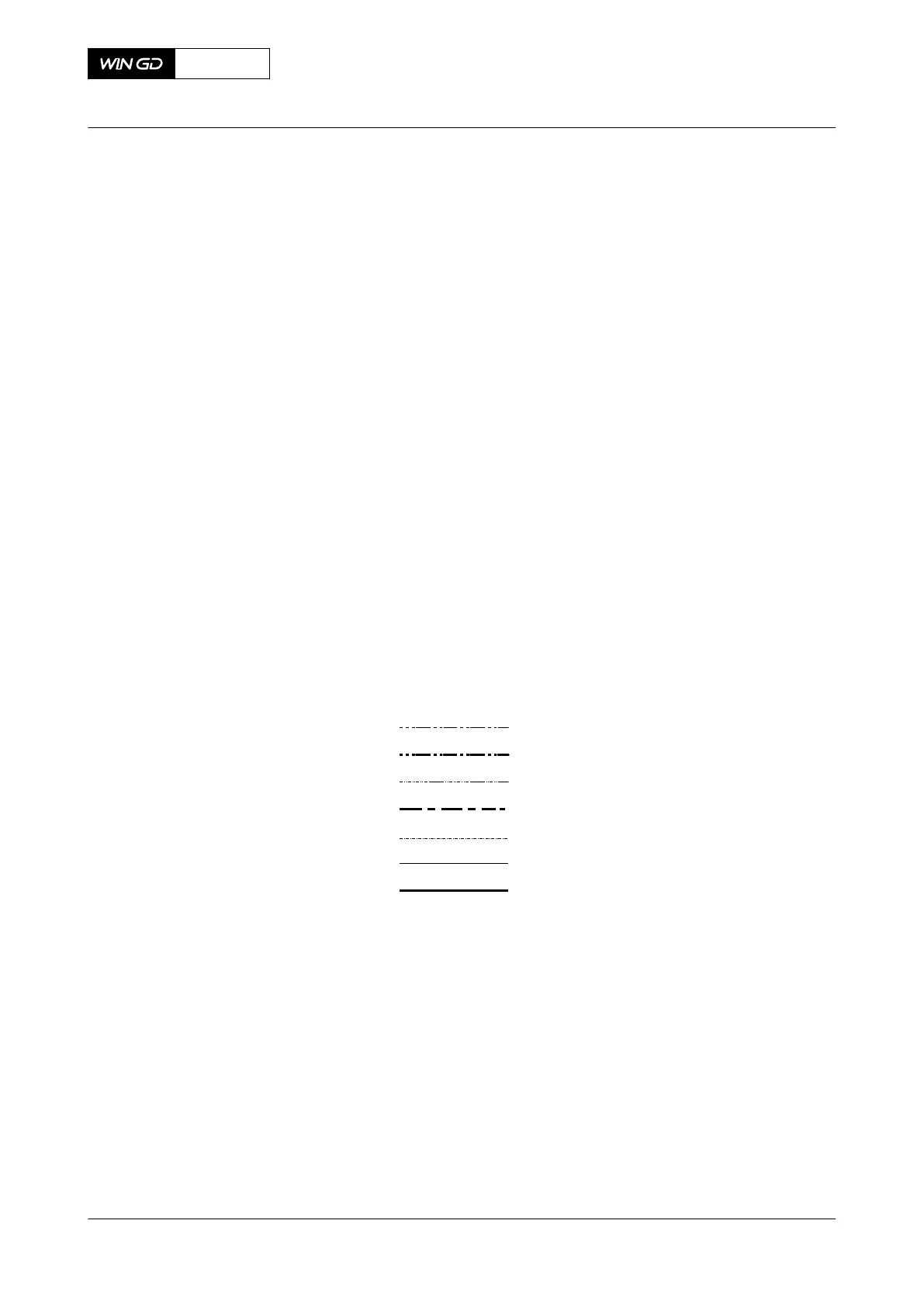
13.1.1.2 Line codes in the engine control diagram
The line codes in the engine control diagram are shown in Figure 13-1.
Fig 13-1 Line codes
001
002
003
004
005
006
007
00208
Legend
001 Low pressure oil circuits 005 Heating
002 High pressure oil circuits 006 Control air circuits
003 Low pressure fuel circuits 007 Starting air circuits
004 High pressure fuel circuits
13.1.1.3 System codes in the engine control diagram
The system codes in the engine control diagram are as follows:
•
Code 10 - Fuel system
•
Code 20 - Oil system
•
Code 25 - Cylinder oil system
X35-B
AA00-0000-00AAA-043I-A
Operation Manual Schematic diagrams - general
Winterthur Gas & Diesel Ltd.
- 456 - Issue 001 2019-10