14
Wizard™ International, Inc., 4600 116th St. SW, PO Box 66, Mukilteo, WA 98275 888/855-3335 Fax: 425/551-4350 wizardint.com
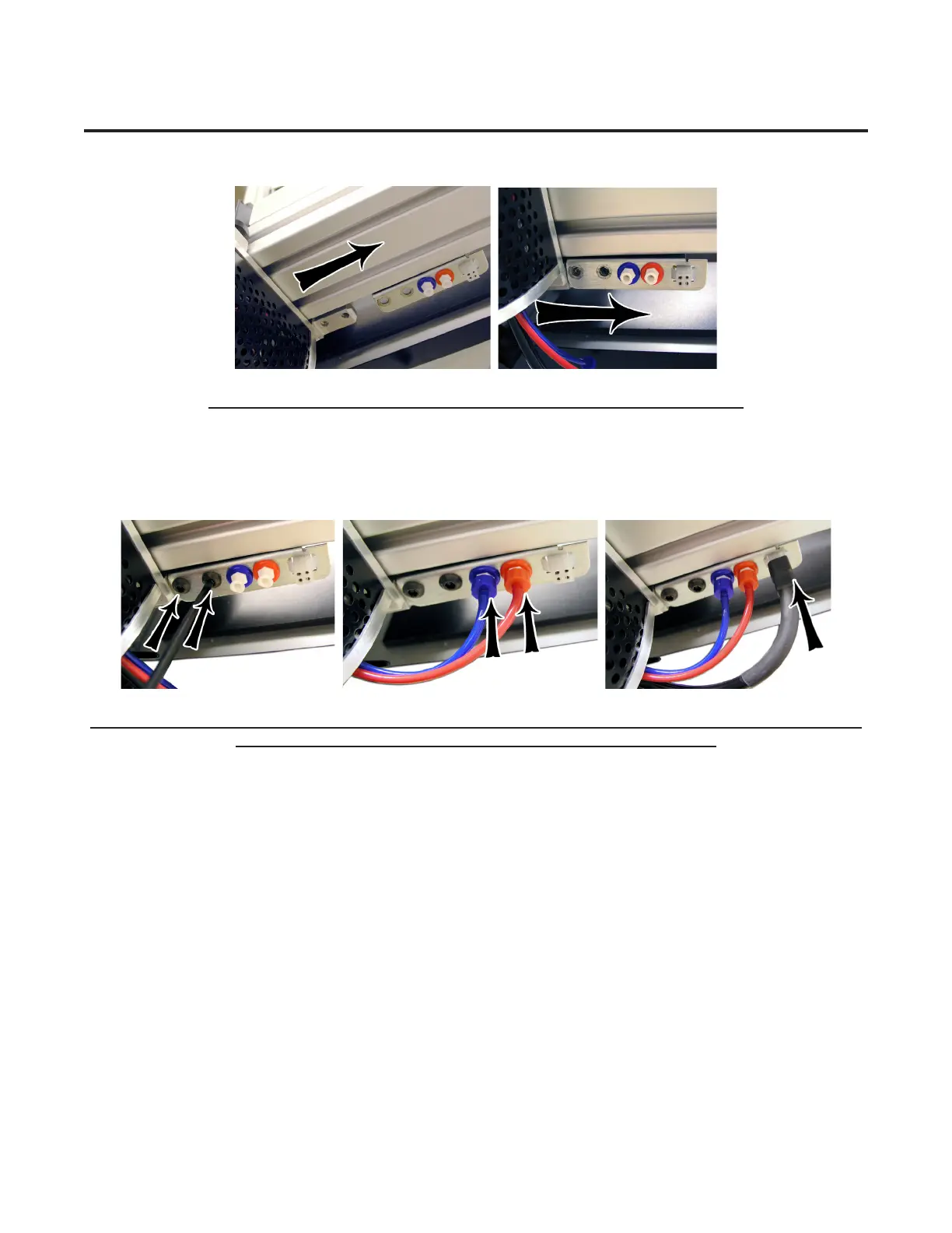
3. Roll the Head up on the Gantry until it lines up to the Head Grabber Arm on the right side of the Gantry. (Fig E-F).
Fig E. Fig F.
Fig E: Head Grabber Arm. Fig F: Holes in Head and Head Grabber Arm lined up.
4. Hold the Head in position, and replace the two 5/32" screws, making sure they go into the Head Grabber Arm and into the
Head(FigG)thentightenrmly.MakesurethattheHeadandtheHeadGrabberArmlineuptogetherneatlytoensurecorrect
tting
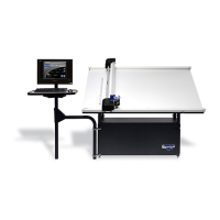
5. Connect the Air to the Head by twisting the two Air Fittings together, matching colors (Fig H). Connect the Head Power
Plug(squareconnection)totheHeadGrabberArm(FigI).
Fig G. Fig H. Fig I.
Fig G: Screw in the two 5/32" screws, making sure they go into the Head Grabber Arm and into the Head. Fig H: Con-
nect the Air Lines, matching colors. Fig I: Connect the Head Power Plug.