\Manuals\GettingStartedManual8500eRev2
10/02/08
17
MatDesigner™ - Getting Started Manual - Model 8500e
Hooking up the Gantry and ST 500 Air Lines
Connecting the Board Cable
*Be VERY CAREFUL when connecting the large Board Cable. Align the
four in-line pins carefully before applying pressure to plug them in. If
forced in incorrectly, they WILL cause malfunction of the Wizard Mat
Cutting system.*
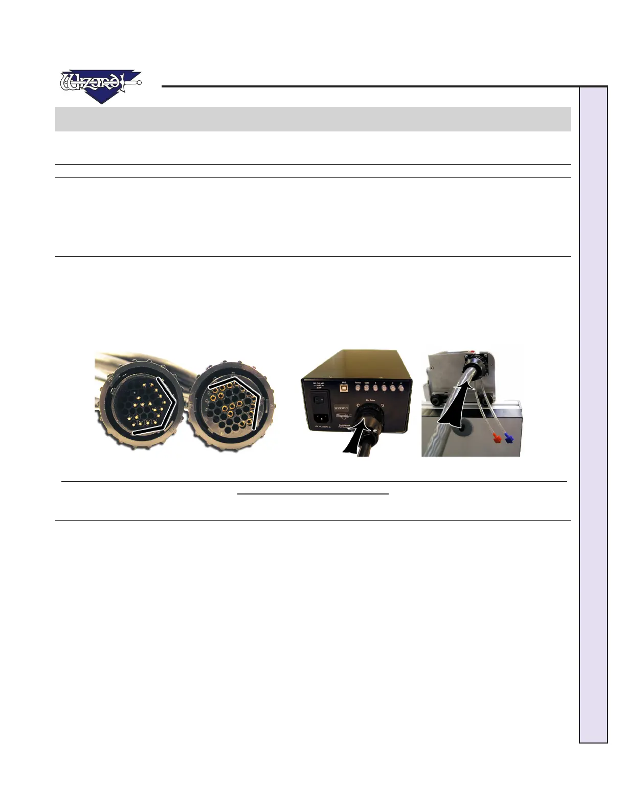
1. The Board Cable connects between the ECU (Electrical Control Unit) and the Gantry. The ECU is the black shoebox-sized
peripheral with a row of LEDs. Connect the large Board Cable (Fig A) to back of the ECU (Fig B) by aligning the four in-line
pins and turning the locking ring until it “seats itself” and locks into place.
2. Connect the other end of the Board Cable to the back of the Gantry in the same manner (Fig C).
3. Move the Gantry to the far right of the Board and back to make sure the Board Cable does NOT get caught on anything. If
the Board Cable is obstructed, this WILL affect your cuts.
Fig A. Fig B. Fig C.
Fig A: Look for the 4 in-line pins on Board Cable. Fig B: Plug one end into back of the ECU. Fig C: The other end is
plugged into the back of the Gantry.
Attaching Air Lines and Air Regulator
1. Go back and make sure that the Air Lines on the back of the Board are not pinched between the Board and the Stand. If you
havenotalreadydoneso,reattachtheAirLinesontheinsideoftheStandArmstoensuremaximumairow(FigA).
2. Connect the Blue Connector from the top of the ST 500 to the Blue Connector/Shut Off Valve of the "Y" Connector (Fig
B).
3.ConnectRedConnectorfromthetopoftheGantrytotheRedConnectorof"Y"Connector;onlyonesidewillt.
NOTE: If you did not install the SL 500, this Red Air Line Connector from the Gantry would plug
into the right side of the Air Regulator.
4. Plug in the Red Air Line Connector from the bottom of the "Y" into the right side of the Air Regulator.
5. Plug the Air Line coming off the left side of the Air Regulator into your main air supply via 1/4" NPT female connector, or
thequickdisconnect,whichevertypeyoupurchased(shownistheblackthreadedttingconnectedtoa1/4"NPTfemaleadap-
tor).Youraircompressorshouldhaveatleast100-120PSI.ItissuggestedthatTeontapebeusedonthethreadsoftheblack
ttingtoreducepossibleairleakage.
6. Strap your Air Regulator, glass bowl down to the left large wall bracket or left stand side with cable ties provided in your
Tool Kit, making sure not to crimp any of the Air Lines.