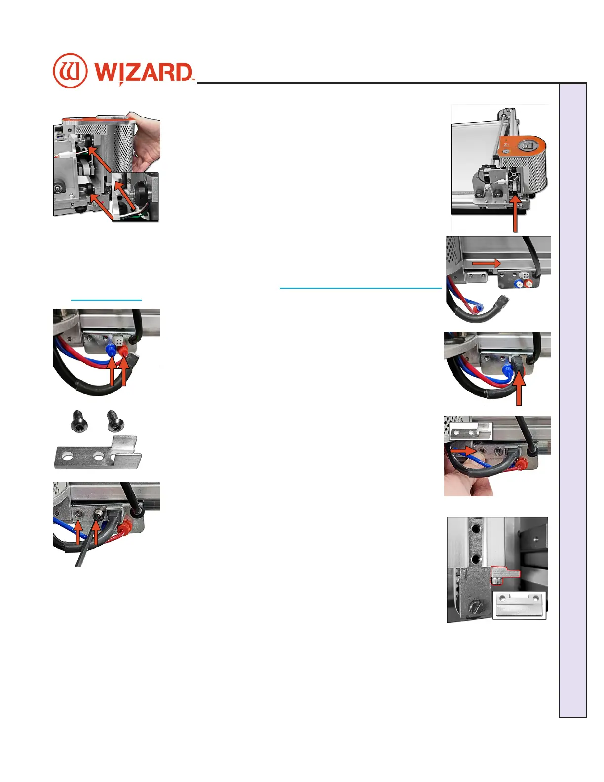
2. Move the gantry to the right edge of the CMC. 2. Move the gantry to the right edge of the CMC.
3. Point the head so that the footblock faces toward the CMC 3. Point the head so that the footblock faces toward the CMC
and the wheels are close to the bottom of the gantry.and the wheels are close to the bottom of the gantry.
4. Line up the wheels on the head to the center channels of 4. Line up the wheels on the head to the center channels of
the gantry arm and ease the head onto the gantry.the gantry arm and ease the head onto the gantry.
5. Roll the head up the gantry until it lines up to the head grabber arm on the right 5. Roll the head up the gantry until it lines up to the head grabber arm on the right
side of the gantry. side of the gantry.
NOTE:NOTE: If you are installing the head and having diculty getting the head wheels If you are installing the head and having diculty getting the head wheels
onto the gantry, see Head Wheel Adjustment at onto the gantry, see Head Wheel Adjustment at https://wizardcutters.atlassian.net/https://wizardcutters.atlassian.net/
wiki/x/YYDHFwwiki/x/YYDHFw. .
6. Connect the air to the head by twisting the two air ttings 6. Connect the air to the head by twisting the two air ttings
together, together, matchingmatching colors. colors.
7. Connect the head power plug (square connection) to the 7. Connect the head power plug (square connection) to the
head grabber arm.head grabber arm.
8. Locate the Head Assembly Power Cable Strain Relief and the 8. Locate the Head Assembly Power Cable Strain Relief and the
two 5/8” screws. two 5/8” screws.
9. Slide the tines of the Head Assembly Power Cable Strain Relief 9. Slide the tines of the Head Assembly Power Cable Strain Relief
around the base sides of the Head Power Plug connection. around the base sides of the Head Power Plug connection.
10. Line up the holes of the Head Assembly Power Cable 10. Line up the holes of the Head Assembly Power Cable
Strain Relief to the holes on the head grabber arm.Strain Relief to the holes on the head grabber arm.
11. Holding the head in position so that the head lines up 11. Holding the head in position so that the head lines up
neatly to the Head Assembly Power Cable Strain Relief on neatly to the Head Assembly Power Cable Strain Relief on
the head grabber arm, screw in the two 5/8” screws, making the head grabber arm, screw in the two 5/8” screws, making
sure they go into the Head Assembly Power Cable Strain sure they go into the Head Assembly Power Cable Strain
Relief and the head grabber arm and then into the head and Relief and the head grabber arm and then into the head and
tighten rmly. tighten rmly.
12. Now that the head is in position replace the Head Stop Plate that was removed 12. Now that the head is in position replace the Head Stop Plate that was removed
earlier. Reattach it to the bottom of the gantry under the belt tensioner with the earlier. Reattach it to the bottom of the gantry under the belt tensioner with the
notched side facing up.notched side facing up.
20-36070-1 GettingStartedManualZ1-70FrameShop
04/03/24
9
Wizard CMC Model Z1: Hardware and Software Getting Started Manual
Wizard™ CMC Model Z1 Hardware and Software Getting Started Guide