EasyManua.ls Logo

Woodward 721 User Manual

Woodward 721
52 pages
To Next Page IconTo Next Page
Page #1 background imageLoading...
Page #1 background image
Operation and Calibration Manual
___
WARNING
23 24 25 26 27 28 29 30 31 32 33 34 35 36 37 38 39 40 41 42 43 44 45 46
23 4 5 6 7 8
9
12 131
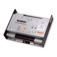
721 DIGITAL CONTROL
W
W
OODWAR
OODWAR
D
D
10 1411 15 16 17 18 19 20 21 22
W
W
D
D
OODW AR
OODW AR
AUXILIARY
COMMON
DISCRETE
COMMON
ABC E GHDF
DISCRETE INPUTS
APPLY +18 TO +40 VDC TO ACTIVATE
+-
+5 VDC
AUXILIARY
DEVICE
POWER
(50mA MAX)
REM
JPR
FOR
+
-
5
VDC
SIGNAL
INPUT
#1
mA
COM
+
-
mA
COM
+
-
mA
COM
+
-
mA
COM
+
-
REM
JPR
FOR
+
-
5
VDC
REM
JPR
FOR
+
-
5
VDC
REM
JPR
FOR
+
-
5
VDC
SIGNAL
INP UT
#2
SIGNAL
INP UT
#3
SIGNAL
INPUT
#4
18-40VDC
18W
SUPPLY
INPUT
+-
CNO
RELAY
OUTPUT
#1
CNO
RELAY
OUTPUT
#1
CNO
RELAY
OUTPUT
#1
+-
ANALOG
OUTPUT
#1
+-
ANALOG
OUTPUT
#2
+-
ANALOG
OUTPUT
#3
+-
ACTUATOR
OUTPUT
+-
SPEED
SENSOR
INPUT#1
+-
SPEED
SENSOR
INP UT#2
+-
LOAD
SHARING
LINES
POWER
AND
CPU OK
ALARM
#1
ALARM
#2
CONTACT PO WER RATING
2.0 AMP RESISTIVE 28VDC
0.1 AMP RESISTIVE 115VAC
721 Digital Speed Control
For Marine Propulsion Application
D/N 9907-717
WOODWARD GOVERNOR (JAPAN). LTD.,
251-1 Nakazawa, Tomisato-city
Chiba - ken, 286 - 0222, Japan
Phone: 81(476)93-4661 Fax: 81(476)93-7939
Manual 26004

Table of Contents

Other manuals for Woodward 721

Question and Answer IconNeed help?

Do you have a question about the Woodward 721 and is the answer not in the manual?

Woodward 721 Specifications

General IconGeneral
BrandWoodward
Model721
CategoryControl Unit
LanguageEnglish

Summary

Chapter 1. General Information

Introduction to 721 Digital Speed Control

Overview of the Woodward 721 Digital Speed Control and its associated manual.

Application of 721 Digital Speed Control

Details the 721 DSC's use in marine propulsion with changeable pitch propeller control.

721 Control Accessories

Describes the hand-held programmer and its connection to the 721 DSC.

Chapter 2. Electrostatic Discharge Awareness

Electrostatic Discharge Awareness Summary

Highlights the need for ESD precautions for sensitive electronic components.

Electrostatic Discharge General Information

Provides detailed precautions for handling electronic controls to prevent static damage.

Chapter 3. Installation

Installation Scope

Outlines chapter content on installation, power requirements, and connections.

Unpacking Instructions

Instructions for careful unpacking and checking the control for damage.

Location Considerations

Requirements for selecting a suitable mounting location for the control.

Electrical Connections

Details on wiring, shielded cables, and control connections.

Power Requirement

Specifies input voltage requirements and nominal power consumption.

Chapter 4. Description of Operation

General Operation Overview

Provides an overview of the 721 Digital Speed Control's features and operation.

Control Dynamics

Explains how control algorithms adapt for transient and steady-state performance.

Speed Reference

Describes how speed reference is controlled locally and remotely.

Load Transfer

Details the process of transferring load between engine-generator sets.

Fuel Limit Function

Explains start fuel limit and maximum fuel limit settings.

Monitoring Control

How to monitor input/output signals using the hand-held programmer.

Chapter 5. Entering Control Set Points

Set Point Entry Introduction

Emphasizes the need for system-specific tuning of set points for optimum performance.

Hand Held Programmer and Menus

Describes the programmer's connection and basic display functions.

Configure Menus

Instructions for accessing and using the configure menus.

Service Menus

Instructions for accessing and using the service menus.

Adjusting Set Points

Details on using keys to increase/decrease values and obtain exact values.

Hand Held Programmer Keys

Explains the functions of various keys on the programmer.

Set Point List

Comprehensive list of configurable set points with min/max/initial values.

Chapter 6. Entering Control Set Points

Configure Menus

Details on setting up parameters via the configure menus.

Service Menus

Explains how to monitor and adjust set points via service menus.

Speed Settings

Describes set points related to engine speed references and rates.

KW Settings

Details set points for engine load and droop settings.

Fuel Limit Settings

Explains set points for limiting actuator output for fuel control.

Display 2 Monitoring

Information on monitoring input/output status via the programmer.

Alarms Monitoring

Describes the menus for monitoring fault status and alarms.

Chapter 7. Major Alarm and Minor Alarm

Major Alarm Conditions

Explains conditions causing a major alarm and its effect on the engine.

Minor Alarm Conditions

Explains conditions causing a minor alarm and its effect on the engine.

Related product manuals