ProTechTPS Total Protection System Manual 26710V1
40 Woodward
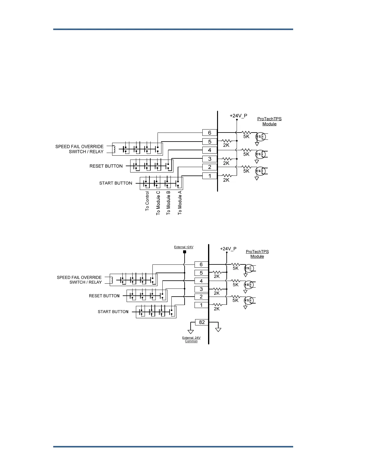
Dedicated Discrete Inputs
Each ProTechTPS model (A, B, C) accepts three dedicated discrete inputs. All
discrete inputs accept dry contacts. Contact wetting voltage is available through
terminals 1, 3, and 5 but an external +24 Vdc source can be used. Refer to
Figure 2-12 for wiring information. In general, an input contact signal must
change state for a minimum of 8 milliseconds for a ProTechTPS module to sense
and register a change in state. The Dedicated Discrete Inputs are Start, Reset
and Speed-Fail-Override. Refer to Chapter 3 (Functionality) of this manual for
information on each discrete input’s functionality.
Figure 2-12a. Example Standard Discrete Input Wiring (Internal Power Option)
Figure 2-12b. Example Standard Discrete Input Wiring (External Power Option)
Configurable Discrete and Analog Inputs
Ten configurable inputs per module (A, B, C) are available to sense discrete
contact input signals or 4–20 mA analog input signals. Depending on the
application’s needs, each input can be configured with the ProTechTPS
Programming and Configuration Tool (PCT) to function as a discrete or analog
input.
To Module B
To Module C
To Control
To Module A