Manual 26710V1 ProTechTPS Total Protection System
Woodward 49
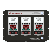
Optional termination resistors for RS-485 communication networks are included
within the ProTechTPS control’s internal circuitry, and only require terminal block
wire jumper(s) for connection to a network, for applications requiring these
termination resistors. Refer to Figure 2-18b for jumper connections.
Figure 2-18b. Serial Com Port Interface Diagram—RS-485
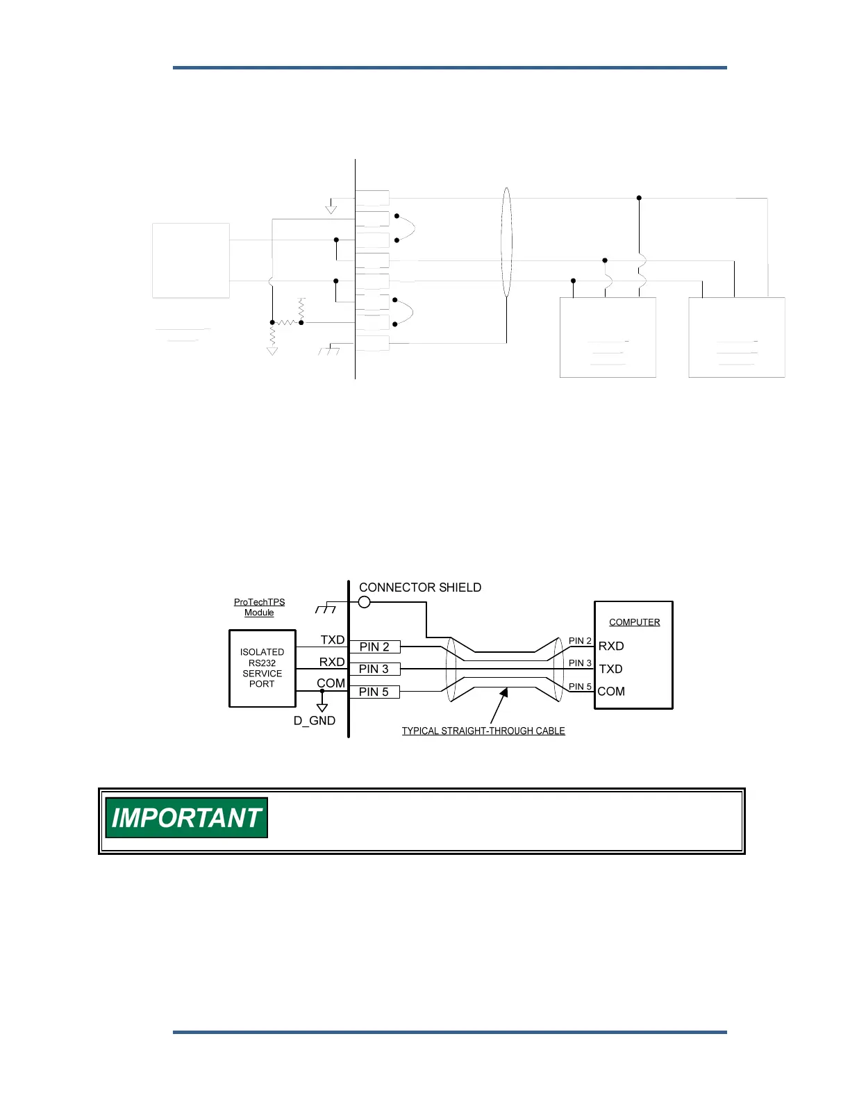
Service Port Communications
One 9-pin Sub-D based service port per module (A, B, C) is available to interface
with a computer for loading program settings into the ProTech and for reading
stored log files from the ProTech using the Programming and Configuration Tool
(PCT). This port is designed to communicate to the computer using a serial DB9
extension (straight-through) type of computer cable.
Figure 2-19. Service Tool Cable/Interface Diagram
The RS-232 serial cable must be disconnected when not in use. The
port is a service port only, it is not designed for permanent
connection.
20
19
18
17
16
15
14
13
ProTechTPS
Module
ISOLATED
RS485 / RS232
PORT
+5V
S_GND
MODBUS
SLAVE
DEVICE
LO HI
OPTIONAL
TERMINATION
JUMPER - HI
HI
LO
OPTIONAL
TERMINATION
JUMPER - LO
COM
MODBUS
MASTER
DEVICE
LOHI
COM