Pre-Installation
23
Greenstar 8000 Life – 6720883866 (2019/04)
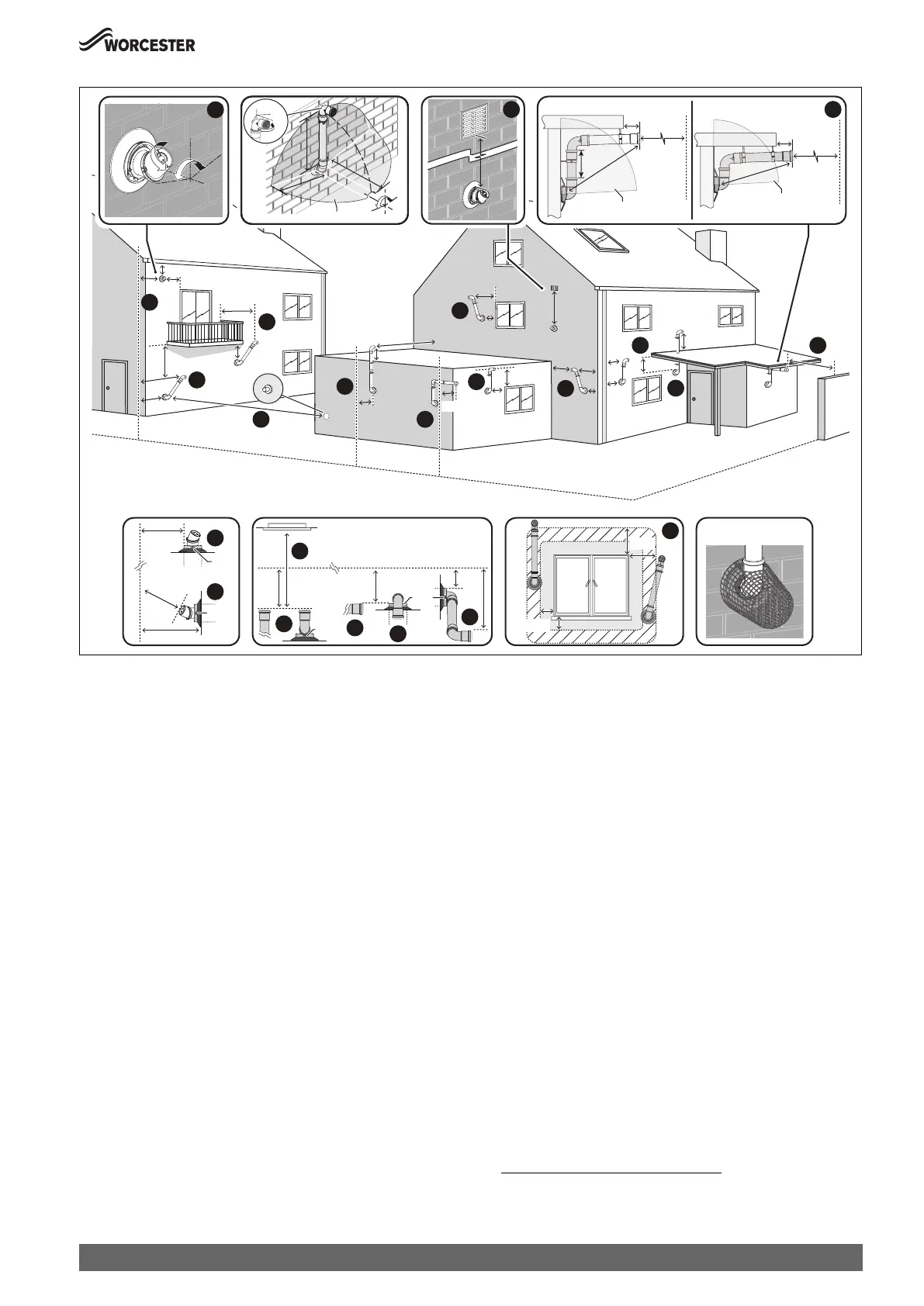
Fig. 31 Plume re-direct and plume management terminal positions
Key to figure 31 - Plume re-direct terminal positions:
[1] This feature allows some basic plume re-direction options on a
standard telescopic horizontal flue terminal.
300mm minimum clearances to a opening e.g. window.
However the minimum clearances to an opening in the direction
that the plume management is facing, must be increased to
1,500mm.
Where the flue is less than 150mm to a drainpipe and plume
redirection is used the deflector should not be directed towards
the drainpipe.
[2] 300mm adjacent to a boundary line, unless it will cause a
nuisance. BS 5440: Part 1 recommends that care is taken when
siting terminal in relation to surfaces or boundary lines.
[3] Where the flow of products of combustion is not at right angles to
the boundary, the 600mm dimension may be measured in the
direction of flow as long as the terminal is not less than 300mm
from the boundary.
[4] When redirecting the flue discharge the terminal end must be at
least 1,500mm from any opening in the direction of the discharge
to prevent combustion products from entering the building.
Key to figure 31 - Plume management terminal positions:
[5] 600mm distance facing a surface or a boundary line, unless it will
cause a nuisance. BS 5440:Part 1 recommends that care is taken
when siting a terminal in relation to surfaces or boundary lines.
[6] Proximity of flue duct outlet to boundaries, 2000mm distance to
an opening in adjacent building facing a terminal. BS 5440: Part
1 recommends that care is taken when siting terminal in relation
to boundary lines.
[7] 300mm adjacent to a boundary line, unless it will cause a
nuisance. BS 5440: Part 1 recommends that care is taken when
siting terminal in relation to surfaces or boundary lines.
[8] 300mm distance from a boundary line to the air intake as long as
the exhaust terminal faces away from the boundary line. The
exhaust terminal must have a minimum 300mm clearance to a
surface below and there must be at least 600mm clearance when
measured horizontally in a straight line from the exhaust terminal
to any other surface.
[9] Plume Management kit air intake can be reduced to 150mm
providing the flue exhaust outlet is no less than 300mm adjacent
to a boundary line.
[10] Above, below and either side of an opening door, air vent or
opening window.
Using a Plume Management kit the air intake measurement can be
reduced to 150mm providing the flue exhaust outlet has a
300mm clearance.
[11] Below balcony or overhange. The air intake clearance can be
reduced to 150mm providing the flue exhaust outlet has a
200mm clearance.
[12] 1,200mm between terminals facing each other
1)
.
[13] Internal/external corners. The air intake clearance can be reduced
to 150mm providing the flue exhaust outlet has a 300mm
clearance.
BOUNDARY LINE
1200
1500
150
150
150
150
25
25
150
300
200
200
200
300
200
300
300
600
300
300
600
300
300
300
100
≥140
≥5
0
0
EXCLUSION ZONE
100
≥5
00
EXCLUSION ZONE
600
600
5
0
0
5
0
0
5
0
0
±80°
EXCLUSION ZONE
±45°
1,500
180°
±80°
BOUNDARY LINE
300
TOP
300
600
TOP
BOUNDARY LINE
600
2000
OPENING
OPPOSITE
300
300
150
TOP
TOP
FLUE TERMINAL GUARD
7 716 191 176
300
150
2
1
2
4
7
8
12
9
11
7
3
8
9
15
5
14
13
10
10
10
6
5
6
0010021676-001
1) 600mm in case two plume management kits are used on opposing terminals.
Each terminal should use a minimum length of 500mm plume management.

 Loading...