Settings in the service menu
Greenstar 8000 Life – 6720883866 (2019/04)
46
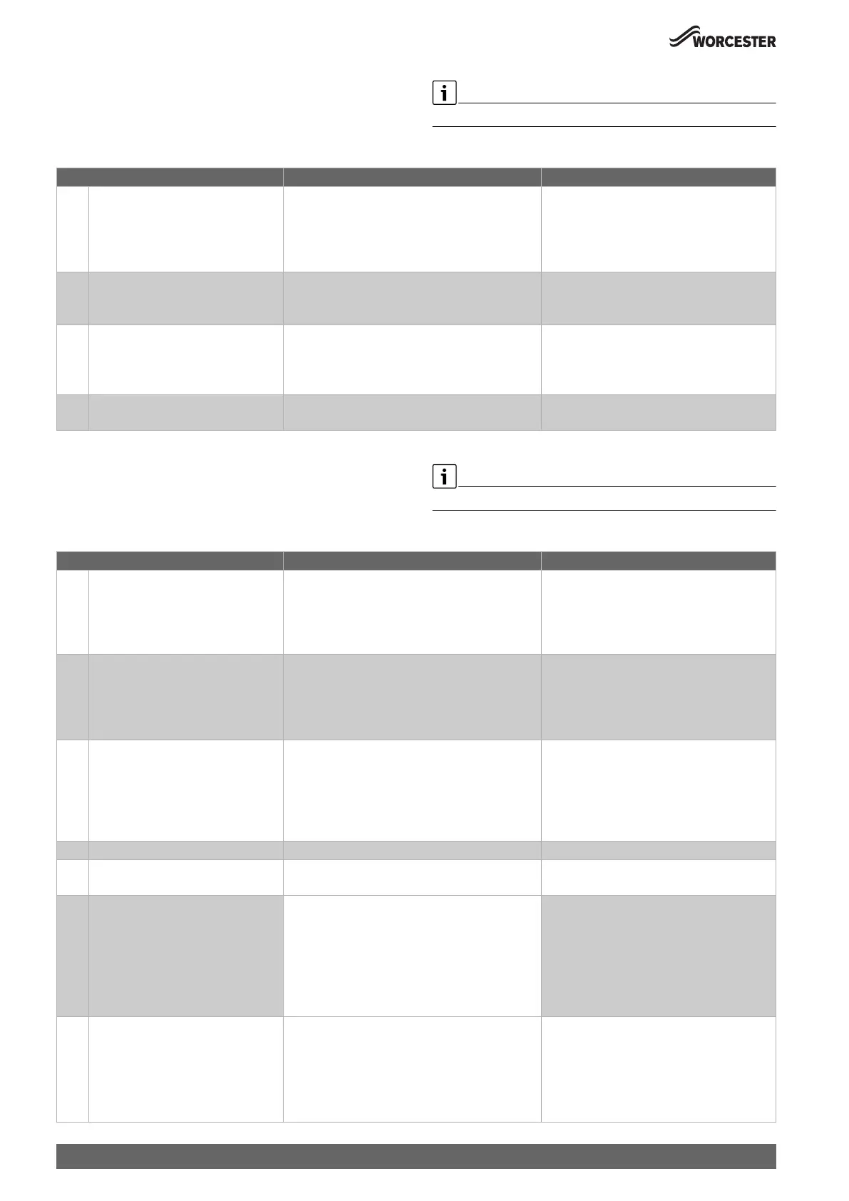
Menu 2 (L.2) Hydraulic settings
▶ Press the ( key and * key at the same time, until L.A is displayed.
▶ Keep pressing the arrow key , until L.2 is displayed.
▶ To confirm the selection: Press the OK key.
▶ Select and set the service function.
The basic settings are depicted as highlighted in the following table.
Table 18 Menu 2: Hydraulic settings
Menu 3 (L.3) Basic Settings
▶ Press the ( key and * key at the same time, until L.A is displayed.
▶ Keep pressing the arrow key , until L.3 is displayed.
▶ To confirm the selection: Press the OK key.
▶ Select and set the service function.
The basic functions are depicted as highlighted in the following table.
Service function L.2 Settings/adjustment range Remark/restriction
2-A1 Low-loss header • 0: No low-loss header present
• 1: Temperature sensor connected at the
appliance
• 2: Low-loss header connected to the module
• 3: Low-loss header without temperature sensor
This setting defines, where the temperature
sensor for the low-loss header is connected.
2-A2 Hot water system • 0: Not installed
• 1: 3-way valve installed
• 2: Cylinder primary pump installed
2-A3 Hydraulic configuration for heating
circuit 1
• 0: No independent heating pump installed
•1:
• 2: Heating pump after low-loss header
• 3: Heating pump connected to the module
This service function will only be available, if
service function 2-A1 is set.
2-A4 Hydraulic configuration heating pump • 0: No pump
• 1: Heating pump
Service function L.3 Settings/adjustment range Remark/restriction
3-b1 Maximum heat output • 50 … 100 % ▶ Set thermal output in percent.
▶ Measure gas flow rate.
▶ Compare measured result with the setting
tables ( page 69). Correct the setting in
the case of any deviation.
3-b2 Standby time • 3 ... 5 ... 60 minutes The time interval determines the minimum dela
between starting and restarting the boiler.
If an outside temperature-controlled heating
controller is connected, this setting is optimised
by the heating controller.
3-b3 Temperature interval for switching off
the burner and switching it on again
• -15 ... -6 ... -2 K ( °C) Difference between current flow temperature
and set flow temperature up to the point when
the burner is switched on.
If an outside temperature-controlled heating
controller is connected, this setting is optimised
by the heating controller.
3-C1 Maximum power on DHW • 50 … 100 %
3-C2 DHW circulation pump • ON
• OFF
3-C3 DHW circulation pump, number of
starts
• 1: 1 x 3 min/h
• 2: 2 x 3 min/h
• 3: 3 x 3 min/h
• 4: 4 x 3 min/h
• 5: 5 x 3 min/h
• 6: 6 x 3 min/h
• 7: permanent
3-C7 Thermal disinfection • OFF
•ON
This service function activates heating up the
storage to 75 °C.
▶ Undertaking Thermal Disinfection
( chapter 7.3).
Thermal Disinfection will be completed after 30
minutes of heating the storage up to 75 °C.

 Loading...