Installation
Greenstar Heatslave II
ErP -
6 720 813 344 (2014/09)22
5.2 Pipework positions and flue opening
Safety
All relevant safety precautions must be undertaken. Protective clothing,
footwear, gloves and safety goggles must be worn as appropriate.
Pipework positions
A to G (below) show the flue and pipe positions:
Fig. 26
Pipework positions:
[A] CH flow 22mm Ø copper (28mm Ø on 25/32kW model)
[B] DHW flow 22mm Ø copper
[C] DCW mains water inlet 15mm Ø
[D] CH return 22mm Ø copper (28mm Ø on 25/32kW model)
[E] Flue outlet
[F] Pressure relief pipe 15mm Ø
[G] Condensate outlet 21.5mm Ø
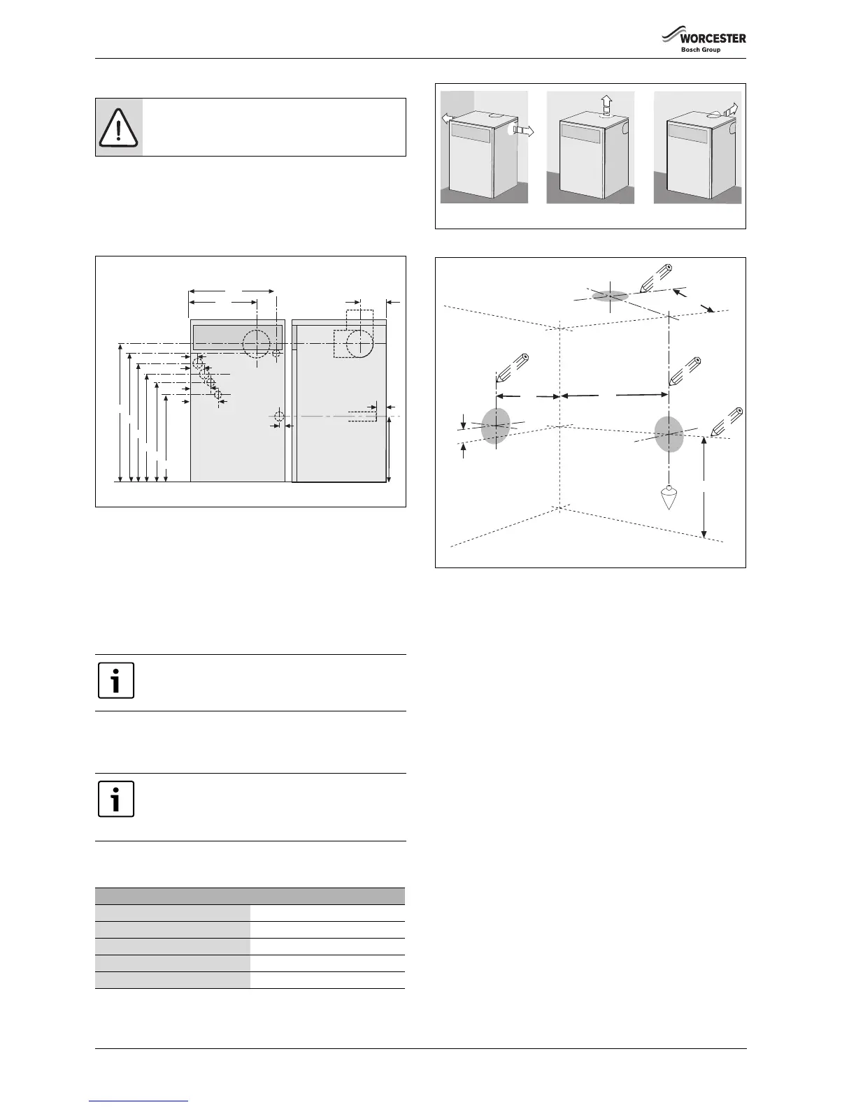
Flue opening
▶ Follow figure 28 to mark the centre of the flue (1, & 2) for rear
opening, (2 & 3) for side opening or (1 & 4) for top opening.
▶ Make an opening (X, Y or Z) through the wall using a core drill or
similar at a size relative to the wall thickness as shown below:
Fig. 27
Fig. 28
[**] IMPORTANT: for horizontal flues, increase this height by 5.2mm
for every 100mm of horizontal length that the flue opening is
away from the boiler.
CAUTION: Ensure there are no pipes, electric cables,
damp proof courses or other hazards before drilling.
For servicing purposes, keep the condensate and
pressure relief discharge pipes away from components
and pipework connections.
All horizontal flue sections must rise away from the boiler
by 52mm per metre to ensure that condensate flows
back into the boiler for safe discharge via the condensate
waste pipe.
125mm Ø flue
Wall thickness mm Flue hole size Ø mm
150 - 240 155
240 - 330 160
330 - 420 165
420 - 500 170
Table 6
 Loading...


