Fault finding and diagnosis
Greenstar Heatslave II
ErP -
6 720 813 344 (2014/09)46
8 Fault finding and diagnosis
8.1 Status cause codes
These cause codes are displayed during the normal operation of the
boiler. They are not faults, they just give information on the current
status of the boiler in real time.
During normal operation various status codes can be displayed by
pressing the service button.
The first screen of the information menu displays the current status
code, this will change as the boiler runs through the various modes and
sequences.
8.2 Information menu
Selecting the Information Menu
The Information Menu is a “read only” menu. Information about the boiler
is displayed here, some of the values are updated in real time to give the
current status of the boiler.
All menus time-out after 2 minutes and the display returns to the
normal operation display, the display backlight turns off after another
30 seconds and goes into stand-by mode.
Double up or down arrows indicate that the menu can only be scrolled up
or down, an up arrow combination indicates position in the menu where
options can be scrolled either up or down.
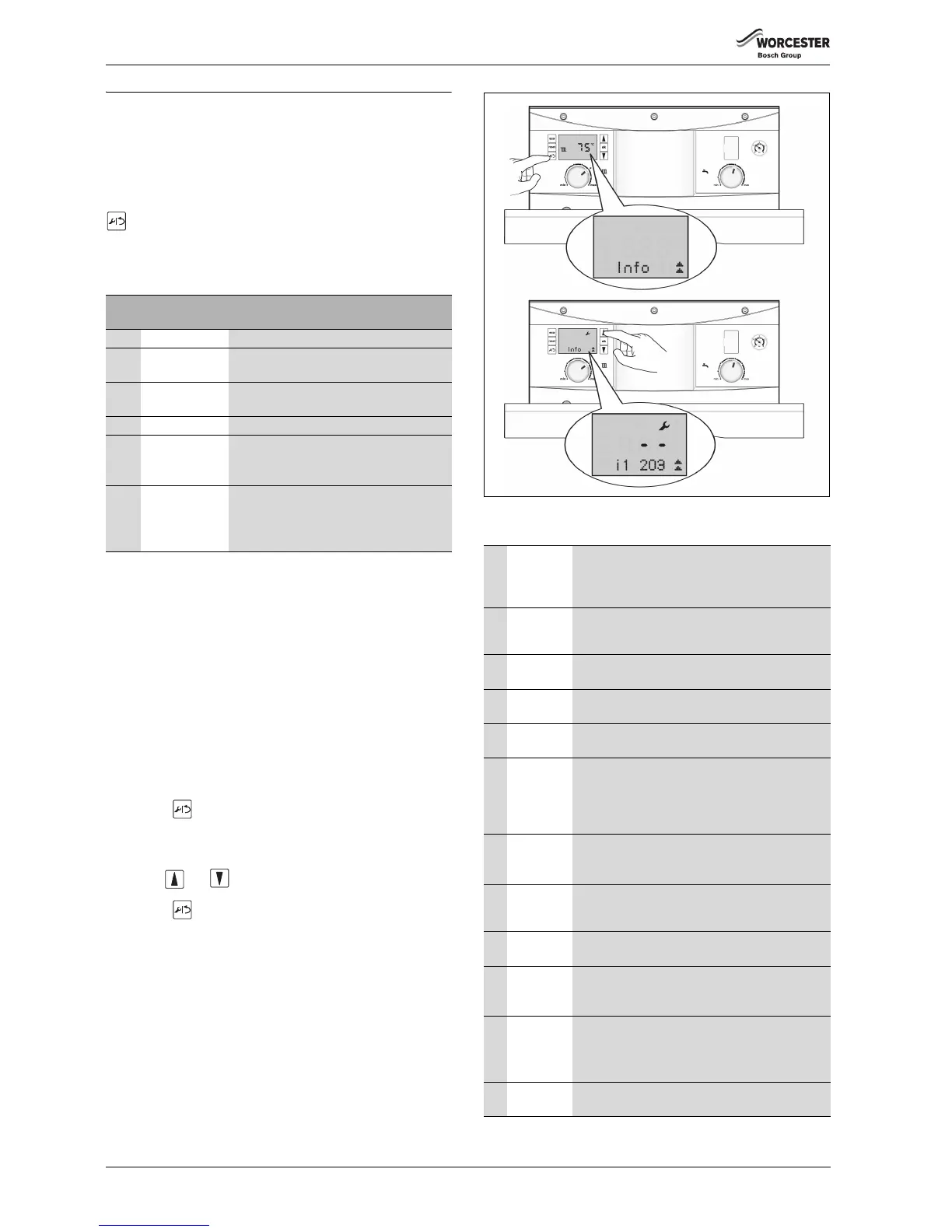
To enter the Information Menu
1. Press the button to enter the Information Menu.
– A 3 figure boiler status code will be displayed alongside the
Information Menu number. Refer to page 34 for a description of
the boiler status codes.
2. Use the and arrow buttons to scroll through the menu
items.
3. Press the button again to exit the Information Menu.
Fig. 83
Information Menu listing
Cause
code
200 CH active The Central Heating system is being heated.
201 DHW active The Domestic Hot Water is being heated/
tank is being heated.
202 CH Anti rapid-
cycle mode
Time delay to prevent rapid-cycling of the
boiler on the room thermostat.
203 System stand-by The boiler has no CH or DHW demands.
270 Power up mode The boiler is ON, warming up and running self
check routines. This lasts approximately
35 seconds.
358 Three way valve
anti-seize
Anti-seize operation. If the diverter valve has
not moved in 24 hours, the valve is operated
to prevent seizing, duration approximately
10 seconds.
Table 13
i1 Current
status
Every operation and mode of the boiler has a related
boiler status code.
The boiler status code is displayed on the screen as
a three figure number.
i2 Last error This can be viewed during normal operation.
Displays the last diagnostic code with boiler status
code.
i3 Maximum
CH output
The maximum possible CH output is displayed in
kW.
i4 Maximum
DHW output
The maximum possible DHW output is displayed in
kW.
i6 DHW flow
rate
The screen displays the current DHW flow rate in
0.1 l/m units.
i7 CH flow
temperature
set point
This is the temperature set point for the primary
flow from the main heat exchanger. This will be zero
during CH demand. Shows the heating control knob
set point unless weather compensation is activated
when it is the calculated set point.
i9 Flow
temperature
This is the flow temperature from the primary heat
exchanger displayed in real time (rounded to 0.5°C
units).
i10 Maximal
temperature
This is the current temperature from the maximum
safety sensor displayed in real time (rounded to
0.5°C units).
i11 DHW flow
temperature
Current DHW flow temperature displayed in real
time (rounded to 0.5°C units).
i12 DHW
temperature
set point
This is the thermal store set point temperature,
selected via the Hot Water control knob on the
fascia.
i13 Thermal
store
current
temperature
This is the thermal store current temperature,
displayed in real time (rounded to 0.5°C units).
i14 DCW inlet
temperature
Current DCW inlet temperature, displayed in real
time (rounded to 0.5°C units).
Table 14
 Loading...


