Installation
Greenstar Heatslave II
ErP -
6 720 813 344 (2014/09)24
▶ All horizontal flue sections must rise by at least 52mm for each metre
(3°) away from the boiler to ensure that condensate flows back into
the boiler for safe discharge via the condensate waste pipe.
▶ The horizontal terminal must be installed at 3° to ensure that the
condensate drains back to the boiler whilst also preventing rain
ingress down the air duct.
Fig. 31
▶ The retaining bracket [M] must be fitted if a flue elbow is used on the
boiler flue outlet.
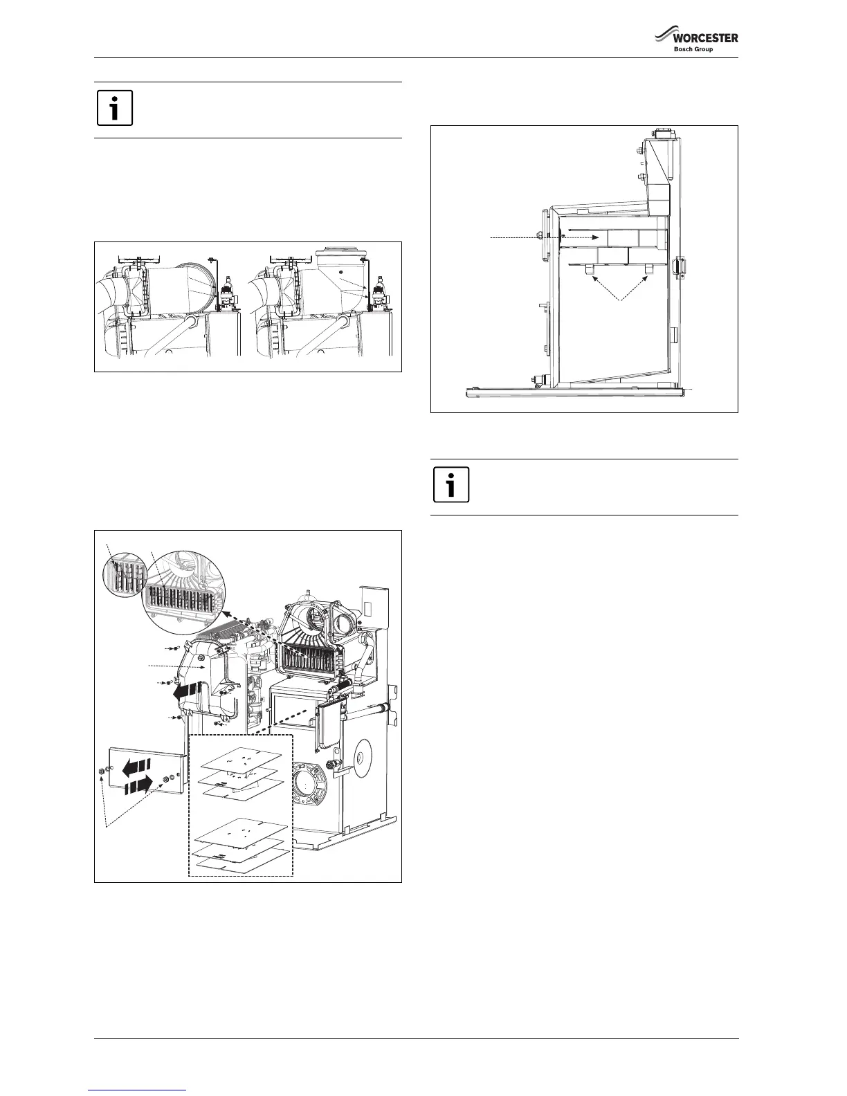
5.5 Combustion chamber
▶ Unscrew screws [G] and remove flue manifold access cover [H].
▶ Check that all the baffles [J] and baffle retainer [K] are correctly
fitted to the secondary heat exchanger.
▶ Remove the retaining nuts and washers [B].
▶ Remove combustion chamber/baffle access door [A].
Fig. 32
▶ Ensure one piece baffle set [C] is in the right location [D], correctly
resting on the baffle rests [F] on either side of the combustion
chamber and pushed securely into place.
Fig. 33
▶ Refit combustion chamber door [A].
The boiler is not designed to take the weight of the flue
system, this must be supported externally to the boiler.
Bracket (M)
Screw (N)
Bracket (M)
Screw (N)
6 720 805 209-10.1TL
 Loading...


