Installation
Greenstar Heatslave II
ErP -
6 720 813 344 (2014/09)26
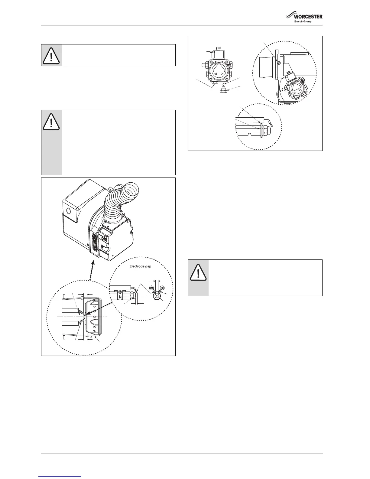
5.7 Oil burner and pump
Oil burner
1. Check that the nozzle (A) and the electrode (B) alignment settings
are correct as shown in figure 35.
▶ Ensure that the nozzle (A) is aligned centrally within the combustion
head (C).
▶ Inspect for any visible defects.
Fig. 35 Nozzle and electrode alignment
Oil pump
Connecting the oil pump for a single pipe system:
▶ The pump is factory set for single pipe operation with the flexible oil
pipe fitted.
▶ Check connections before use.
Converting the oil pump for a double pipe system:
1. Check the inlet pipe connection (1).
▶ Unscrew return plug (2).
▶ Screw in by-pass screw (3) which is attached to the oil pump.
2. Connect the flexible oil pipe return hose (not supplied) to the oil
pump and return pipe fixing and tighten to secure (for routing see
figure 34.
Fig. 36
[1] Inlet pipe connection
[2] Return plug
[3] By-pass screw
[4] Brass air deflector washer (12/18 models only)
[5] Locating circlip
[6] Electrode fixing screw
5.8 Refitting components
Refer to figure 37
1. Align burner combustion head into the boiler collar.
▶ Locate the burner retainer [A] over the threaded lug on the collar [B],
push the burner firmly into the flange and secure in place with the
retaining nut [C]. Tighten sufficiently but do not over tighten.
▶ Check that the burner is seated correctly on its mounting flange and
that the oil hose/s are routed correctly as shown on page 25.
2. Refit the flexible air duct and secure with clip [D].
3. Plug burner lead [F] into connector [G].
4. Swivel the expansion vessel [H] back into position taking care not to
kink the flexible hose or snag electric cables.
5. Refit control box.
▶ Rotate the box towards you [J].
▶ Slide control box drawer back into position.
6. Refit panels.
▶ Locate bottom edge of panel [K] onto the bottom supporting ledge
[L] on the boiler.
▶ Secure panel [K] with screws [M].
CAUTION: MAINS SUPPLIES
▶ Isolate the oil & water mains supply before starting
any work and observe all relevant safety precautions.
NOTICE: IMPORTANT INFORMATION
▶ Before removing or fitting a nozzle (A), loosen screw
(6 figure 36) and move the electrodes (B) forward.
After refitting check that the electrode gaps are
correct, as shown in figure 35.
▶ Whenever replacing the combustion head, ensure
that the photocell is lined up with the sight hole.
▶ The 12/18 model has a brass deflection washer and
locating circlip behind the nozzle. These must be in
place for the correct operation of the burner.
 Loading...


