Installation
Greenstar Heatslave II
ErP -
6 720 813 344 (2014/09) 23
5.3 Boiler installation
▶ Lift the top panel [A] upwards to disengage the ball stud connections
[B] and remove.
▶ Remove the installation and literature packs.
▶ Pull control box drawer [C] forward.
▶ Depress the two levers [D], one on either side, to release the control
box and pull fully forward.
▶ Swivel the complete control box assembly upwards.
▶ Remove front panel securing screws [F] from each side.
▶ Lift panel [G] slightly to free it from the lip [H] on the baseplate and
remove.
▶ Unplug burner lead [J] from control box [C].
▶ Swivel the expansion vessel [K] on its support bracket out of the
boiler taking care not to snag any electrical cables or kink the flexible
hose.
▶ Loosen air duct pipe clip [N] and disconnect the air duct pipe.
▶ Unscrew burner retaining nut [O] and remove the burner [P] and
store safely away from the boiler.
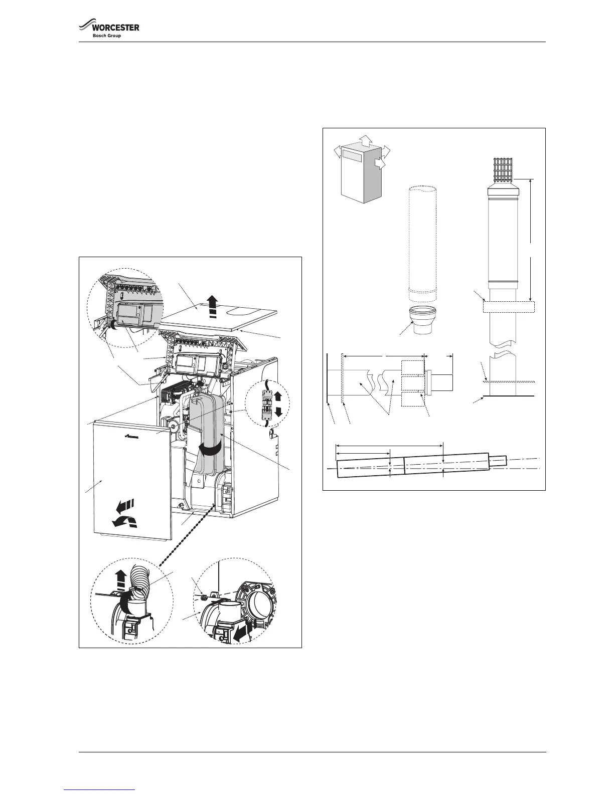
Fig. 29
5.4 Flue installation
The flue can exit the boiler from outlets A, B, C or D allowing vertical (RS)
and horizontal (RS low or high level) flues to be fitted. (CF position 'A'
only).
Refer to the separate flue installation instructions supplied with the flue
kits available for this boiler:
Fig. 30
[E] Boiler outer casing
[F] Outer flue tube
[G] Outlet/elbow connection
[H] Outside wall/roof
[K] CF adaptor
[L] Effective length of the flue
Installation notes
▶ When connecting a flue elbow directly to the boiler flue outlet, loosen
the flue elbow retaining bracket screws [N] before fitting the flue
elbow. Insert the flue elbow with its clamp loosely fitted, then tighten
the bracket screws [N]. Clamp the elbow when adjusted to its
required orientation.
If using an extension or horizontal terminal onto the boiler flue outlet,
remove the flue elbow retaining bracket [M].
▶ Ensure all flue seals are in good condition and seated properly.
▶ To ease assembly of flue components, grease seals lightly with the
solvent-free grease supplied.
▶ A clamp should be installed for every 1m and at every change of
direction.
 Loading...


