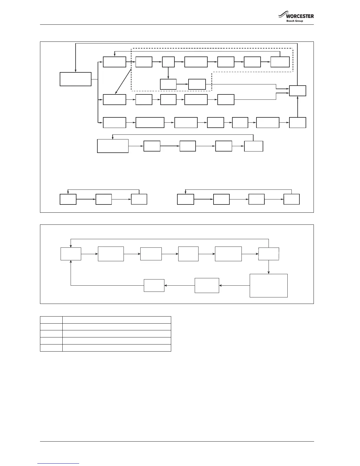
Appliance automatic frost
protection ( monitors
PHE, flow and internal
tank sensors)
PHE OR Flow
sensor below
8°C
Tank will scavenge
heat after any burn to
heat tank to 10°C
3WV to CH
Pump
ON
PHE OR Flow
sensor below
9°C
Pump OFF
after 5
minutes
3WV to
DHW
Waiting period
of 25 ninutes
PHE AND
Flow sensor
above 9°C
Pump OFF
(min run time
1minute)
PHE OR Flow
sensor below
4.5°C
3WV to CH
Pump ON
Burner ON
PHE sensor
above 15°C,
Burner OFF
Pump OFF
after 3
minutes
Internal tank
sensor 8°C
or less
3WV to
DHW
Pump ON
Burner ON
Tank sensor
above 10°C,
Burner OFF
Pump OFF
after 4
minutes
Internal tank
sensor 5°C
or less
3WV to
DHW
External 230V frost
thermostat/s ON, (wired
between FR & FS)
3WV to CH
Pump ON
for 5
minutes
3WV to
DHW
Waiting period
of 25 minutes
Normal
operation
Pump has
not run for
24 hours
Pump run
for
10
seconds
Normal
operation
3WV has
not moved
for 24 hours
W
hen
pump
is
OFF
3WV
operated
twice
6 720 805 209-72.1TL
Note: During system frost protection the external frost stat only activates circulation of the water to protect the vulnerable pipework,
the burner will be activated if either internal sensor temperature drops below 4.5°C.
The frost protection system may be activated on commissioning the appliance for the first time during cold weather where
the water used to fill the system is below 8°C or the property has cooled down to below 8°C.
Check the FLOW TEMPERATURE on the programmer to comfirm this situation.
THE CAUSE CODE WILL BE 203 AND THE BLUE LIGHT WILL BE OFF DURING ALL FROST PROTECTION FUNCTIONS.
Component antiseize functions:
Frost Protection System:
Frost Protection
Appliance:
Key
PHE Primary heat exchanger.
3WV 3 way valve (diverter valve).
FS Appliance connection frost stat supply (230 V)
FR Appliance connection frost stat return (230 V)
 Loading...


