Pre-Installation
Greenstar Heatslave II
ErP -
6 720 813 344 (2014/09)12
Maximum pipe run for double pipe sub-gravity fed system
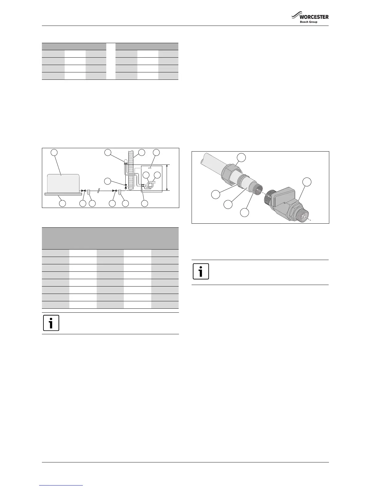
4.3.3 Single pipe suction lift with de-aerator:
Maximum suction height 3.5 metres. The oil tank [1] must be positioned
below the oil pump [9]. Create an inlet and return loop between the de-
aerator [12] and oil pump [9].
A non-return valve must be incorporated within the de-aerator or fitted
to the oil line between the oil storage tank [1] and the de-aerator [12].
A top feed oil tank fitted with a de-aerator using an internal non-return
valve should have any non-return valves fitted in the base of the tank to
the suction line removed to assist purging air from the oil line.
Fig. 6 De-aerator feed
Maximum pipe run for single pipe suction lift with de-aerator
4.3.4 Pipework
▶ Refer to the oil supply sections Single pipe gravity feed
system: 4.3.1, Double pipe sub-gravity feed system: 4.3.2 & Single
pipe suction lift with de-aerator: 4.3.3 for oil supply pipework
configurations.
Oil supply pipework considerations:
• Lay the oil supply pipe as straight and level as possible to avoid air
pockets and unnecessary friction losses.
– Route away from the boiler access door or other hot surfaces.
• Install a manual isolating valve to the oil supply pipe, as close to the
oil storage tank as possible.
• Fit an oil strainer and water separator to the oil supply pipe, near the
oil storage tank.
– Fit an additional oil filter (70 μm max filtration size) close to the
boiler, but not inside the boiler casing.
• Fit a fire valve in accordance with BS 5410.
– The fire valve should be fitted externally to the building with the
fire valve sensor located within the appliance case.
– A fire valve with a shut off temperature of 85°C or higher must be
fitted to avoid the possibility of nuisance shut offs.
– A capillary type valve provides a neat and simple installation.
Alternatively, a fusible link or electrical system may be used.
• Under no circumstances should a combination isolating/fire valve be
used as the sole fire protection device.
4.3.5 Boiler isolation valve
▶ Use copper pipe of the correct diameter according to the information
shown in oil supply sections 4.3.1, 4.3.2 & 4.3.3.
– If using soft copper pipe (R220) with a compression fitting, an
insert must be used to prevent the pipe from collapsing or
distorting when the fitting is tightened.
▶ Slide nut [1] and olive [5] onto the oil supply pipe [4].
▶ Slide insert [3] into the pipe.
▶ Offer the pipe to the fitting [2] and tighten the nut [1].
Fig. 7 Isolation valve bracket removed for clarity
▶ Use flexible hoses to connect from the boiler isolation valve/s and the
oil pump.
4.4 Water systems and pipework
Primary system plastic pipework
• Any plastic pipework used for the CH system must have a polymeric
barrier, complying with BS 7921 and installed to BS 5955 with
1000mm (minimum) length of copper or steel pipe connected to the
boiler.
• Plastic pipework used for underfloor heating must be correctly
controlled with a thermostatic blending valve limiting the
temperature of the circuits to approximately 50°C with 1000mm
(minimum) length of copper or steel pipe connected to the boiler,
and a 20 K differential must be maintained at the appliance.
Primary system/connections/valves
• Do not use galvanised pipes or radiators.
• All system connections, taps and mixing valves must be capable of
sustaining a pressure of 3 bar.
• Radiator valves should conform to BS 2767:10.
• All other valves should conform to BS 1010.
• An automatic bypass valve must be connected between the heating
flow and return where TRVs are used on all radiators, fitted to give at
least a 3 metre circuit when activated.
• Drain cocks are required at all the lowest points on the system.
• Air vents are required at all high points on the system.
Sealed primary system
• Where the system volume is more than 180 litres at 0.5 bar or
exceeds 2.65 bar at maximum heating temperature an extra
Head (m) 10mmØ 12mmØ Head (m) 10mmØ 12mmØ
050100 2.0 26 66
0.5 44 100 2.5 20 50
1.0 38 95 3.0 14 37
1.5 32 80 3.5 8 22
FUEL FLOW RATE
2.5kg/h 5kg/h 10kg/h 10kg/h
Head (m) 8mmØ 8mmØ 8mmØ 10mmØ
010055 26 100
0.5 95 45 23 100
1.0 80 40 20 90
1.5 70 35 17 75
2.0 60 30 14 65
2.5 45 25 11 50
3.0 35 15 8 35
3.5 25 10 5 20
The table and illustration above is a guide only and does
not in any way override the de-aerator manufacturer’s
instructions
 Loading...


