Installation
Greenstar Heatslave II
ErP -
6 720 813 344 (2014/09)28
Mounting optional Plug-In controls
Removing the blanking plate
The control panel must be pulled fully forward to gain access to the top
cover panel (refer to page 23 for access to the control panel).
1. Release the 3 screws [A] and remove the access cover [B].
▶ Use the tab [C] to lift and also press down on the bottom edge of the
blanking plate and at the same time push the blanking plate upwards
to release it from the clips on the control panel.
▶ Pull the blanking plate forwards to remove.
Fitting the programmer/timer
2. If your programmer has a ribbon cable, connect the ribbon cable to
the socket [D] in the control panel, ensuring the cable will fit into the
recess [E] in the control panel.
If your programmer does not have a ribbon cable then the EMS
connections will be utilised to make connection to the boiler.
▶ Align the clips on the back of the programmer/timer with the slots [G]
in the control panel and push in to engage the clips into the 4 slots.
▶ Pull the programmer/timer downwards to secure into place.
▶ Replace the top access cover [B] securing in position with the 3
screws [A].
Fig. 39
Fig. 40
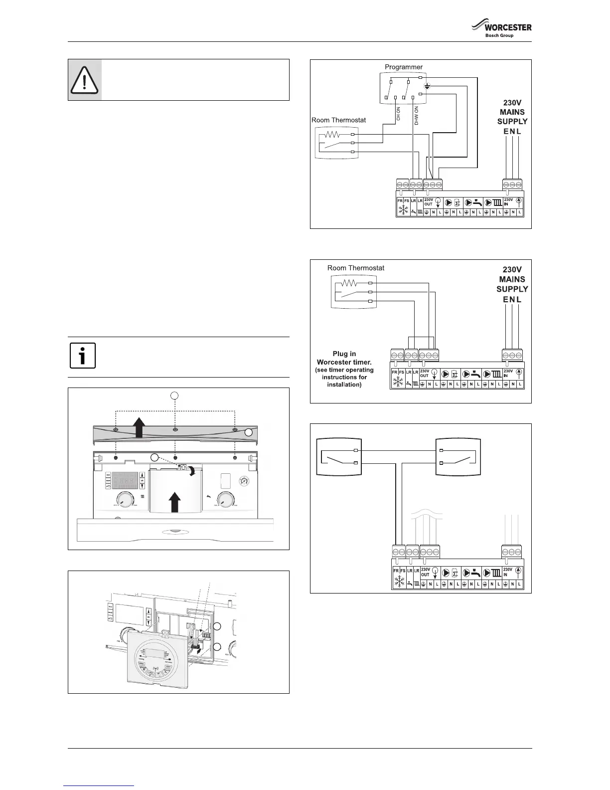
Fig. 41 External 230 V Twin Channel Programmer and Room
Thermostat
Fig. 42 Room Thermostat and Plug In Twin Channel Programmer
Fig. 43 Optional External 230 V AC Frost Stat Connection for
protection of system pipework in unheated air space
▶ Connect frost thermostat cables to terminals FS & FR.
– These connections are not polarity sensitive.
– The Boiler internal frost protection will bring on the burner if
required.
DANGER: 230 Volts
Isolate the mains electricity supply before starting any
work and observe all relevant safety precautions.
The 230V links (L OUT to CH LR & L OUT to DHW LR) are
required for facia mounted programmers to operate.
 Loading...


