Commissioning
Greenstar Heatslave II
ErP -
6 720 813 344 (2014/09) 33
▶ Switch off the boiler.
Clean the oil pump filter
▶ The internal filter is accessed by removing the oil pump cover
▶ Remove the oil pump filter, clean with Kerosene and refit
▶ Safely dispose of the container/discharge
Fig. 55
2. Fit a suitable pressure gauge to port [A] on the oil pump.
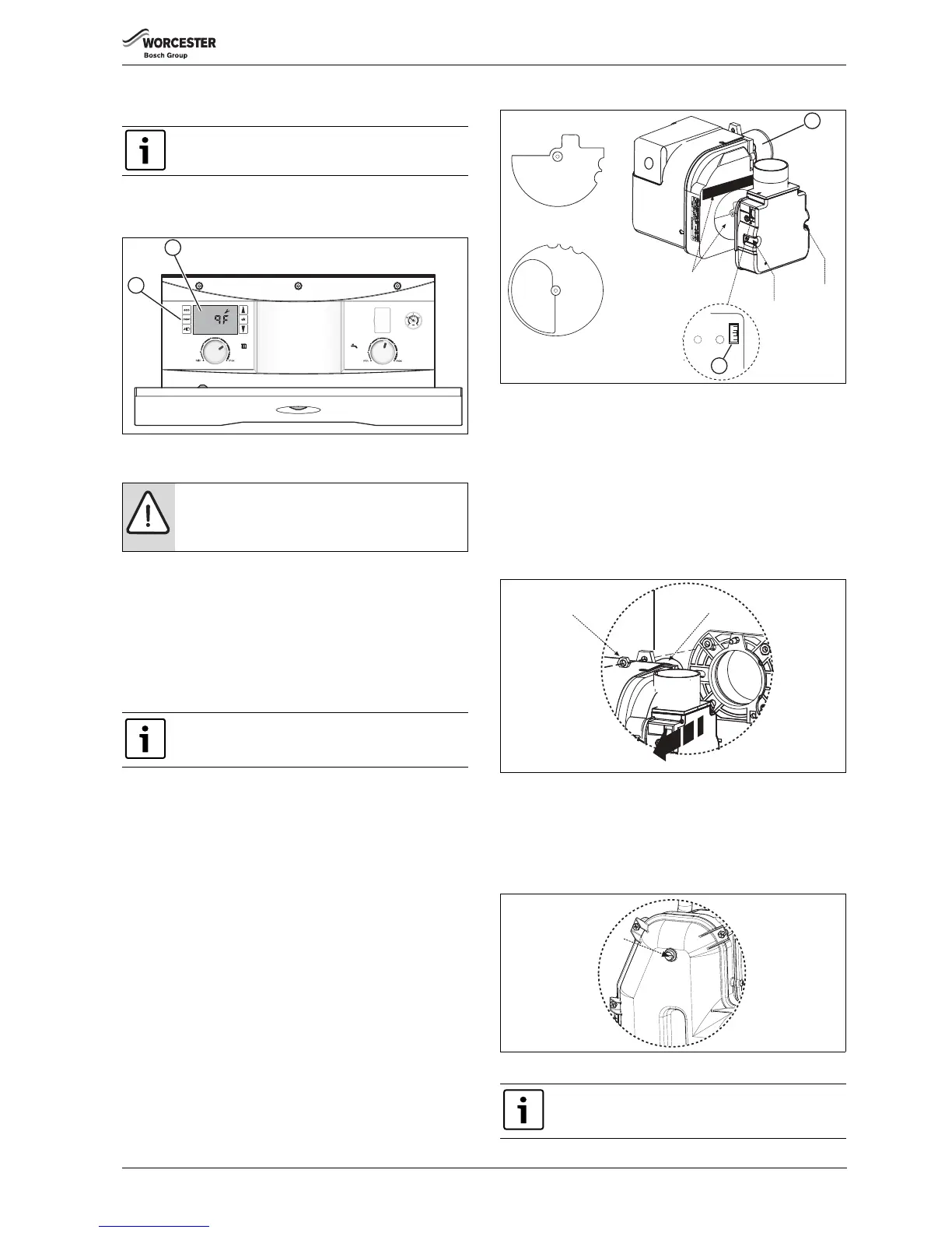
▶ 12/18 & 18/25 - RIELLO RDB 2.2
Adjust position of the air damper disc to suit the burner output
( table 8 on page 36), located as shown in figure 56. Access is by
loosening the two star screws (SC) to release the air inlet manifold.
▶ 25/32 - RIELLO RDB 2.2
No damper disk is fitted to the 25/32kW burner.
▶ Adjust the air shutter [L] (see figure 56) and pump pressure [B] as
shown in figure 54. The burner should ignite following a pre-ignition
period of approximately 15 seconds.
Boiler lockout
If the burner fails to establish a normal firing pattern or flame failure
occurs the flame monitoring photocell mounted in the burner body will
alert the burner control box to shut the burner down and provide a safe
lockout state indicated on the control panel LCD display [J] by code
9F 855.
▶ Wait two minutes then press the lockout reset button [K] to initiate
another start sequence.
▶ Repeat procedure until a flame is established.
Fig. 56
3. Start and run for 3 minutes then switch off.
▶ Check for after-spurting from the nozzle, indicated by oil saturation
on the combustion head [G].
If after-spurting occurs:
▶ Release the burner retainer nut [H].
▶ Remove the burner, combustion head [G]. and electrodes, hold the
burner vertical to unscrew the nozzle and fill the nozzle holder with
oil.
▶ Refit nozzle, electrodes, combustion head [G] and the burner.
▶ Restart and run for 3 minute intervals until after-spurting stops.
Fig. 57
1. Start and run for 20 minutes.
▶ Check that the oil pressure is set according to table 8 on page 36
▶ Remove sampling point plug [J] to check the smoke reading is
between 0-1. If the smoke level is above 1, check the combustion
settings are correct and the oil nozzle is in good condition.
Fig. 58
If debris is found, then the oil supply system must be
checked for the source of debris before the boiler is
commissioned.
NOTICE:
If changing the burner output, ensure the position of the
air damper disk is correct for the desired output.
Refer to table 8.
The MO535 MRF control box has an 3.5 second delay
before the start of the pre-ignition.
 Loading...


