Service and Spares
Greenstar Heatslave II
ErP -
6 720 813 344 (2014/09) 39
▶ Check that the condensate system is not obstructed, clean and refill
the condensate trap.
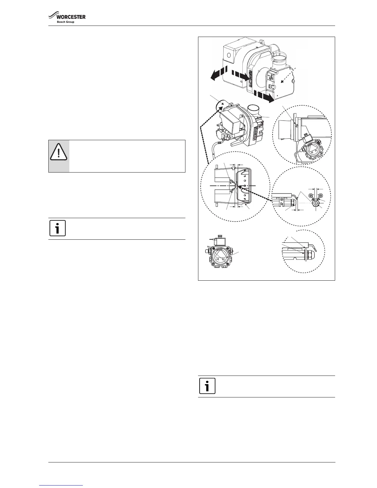
Clean the burner
▶ Loosen the 2 hex head screws and remove the air intake cover [A]
and clear any debris from the air intake and air damper.
▶ Disassemble the burner to allow access to the fan impeller.
▶ Check the condition of the gaskets between these parts and replace
if necessary.
▶ Note the position of the air damper adjustment and check the air
damper moves freely.
▶ Clean both sides of the fan impeller and remove any debris from the
burner housing.
▶ Check that the impeller rotates freely.
▶ Reassemble the components.
▶ Remove the combustion head [B] and thoroughly clean any deposits.
▶ Remove the nozzle [C].
▶ Check the nozzle holder is clear of any debris and clean if necessary.
▶ Fit a new oil nozzle [C].
DO NOT dismantle the nozzle and DO NOT clean the nozzle tip.
▶ Check the electrodes [E] and reset if necessary as shown in
figure 73.
▶ Refit the combustion head [B]. Check that the nozzle [C] is central in
the combustion head [B] and the head settings are as shown. Ensure
that the photocell is lined up with the sight hole.
▶ Withdraw the photocell [G] from its housing and wipe clean.
▶ Remove the oil pump internal filter, clean in Kerosene and
reassemble.
The internal filter is accessed by removing screws [H] and the oil pump
cover [J].
▶ Replace the standard flexible oil line/s at every annual service to
prevent the possibility of leakage due to ageing.
▶ Reassemble the burner components.
▶ Check the O-ring seal located around the combustion head and
replace if necessary. This seal must be in good condition, seal failure
will cause flue gases to escape into the room.
Fig. 73 Burner detail
External oil filter
▶ Remove the paper element from the external oil filter and replace it.
If the filter contains a washable element, thoroughly clean in
Kerosene and reassemble into the filter.
Clean the boiler - Manifold access
Refer to figures 74 and 75.
▶ Release screws [A] to remove the flue manifold access cover [B] and
clear any debris.
▶ Check the flue system and clean if necessary.
▶ Remove the baffle retainer [C] and baffles [D] from the secondary
heat exchanger.
▶ Check and clean the secondary heat exchanger surfaces.
▶ Check the condensate route [E] is clear.
▶ The condensate trap [F] should be removed and cleaned.
▶ Release the pipe locking tab [G] and disconnect the flexible pipe [H]
from the top of the trap and move the flexible pipe up away from the
trap.
▶ Release the trap locking tab [I] and move the trap up and back to
remove from its mountings.
▶ Clean the trap by flushing with water.
NOTICE:
Before removing or fitting a nozzle [C], loosen screw [D]
and move the electrodes [E] forward.
After refitting check that the electrode gaps are correct,
as shown in figure 73.
The 12/18 model has a brass air deflection washer and
locating circlip behind the nozzle. These must be in place
for the correct operation of the burner.
Do not use wire brushes and cleaning agents to clean the
stainless steel secondary heat exchanger components.
D
G
B
5mm
5mm
C
E
B
3.5-4.0mm
C
E
E
2.0 - 2.5mm
C
Electrode gap
 Loading...


