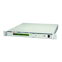
Figure 1: Block Diagram of the Upconverter
2.3.2 Signal Flow
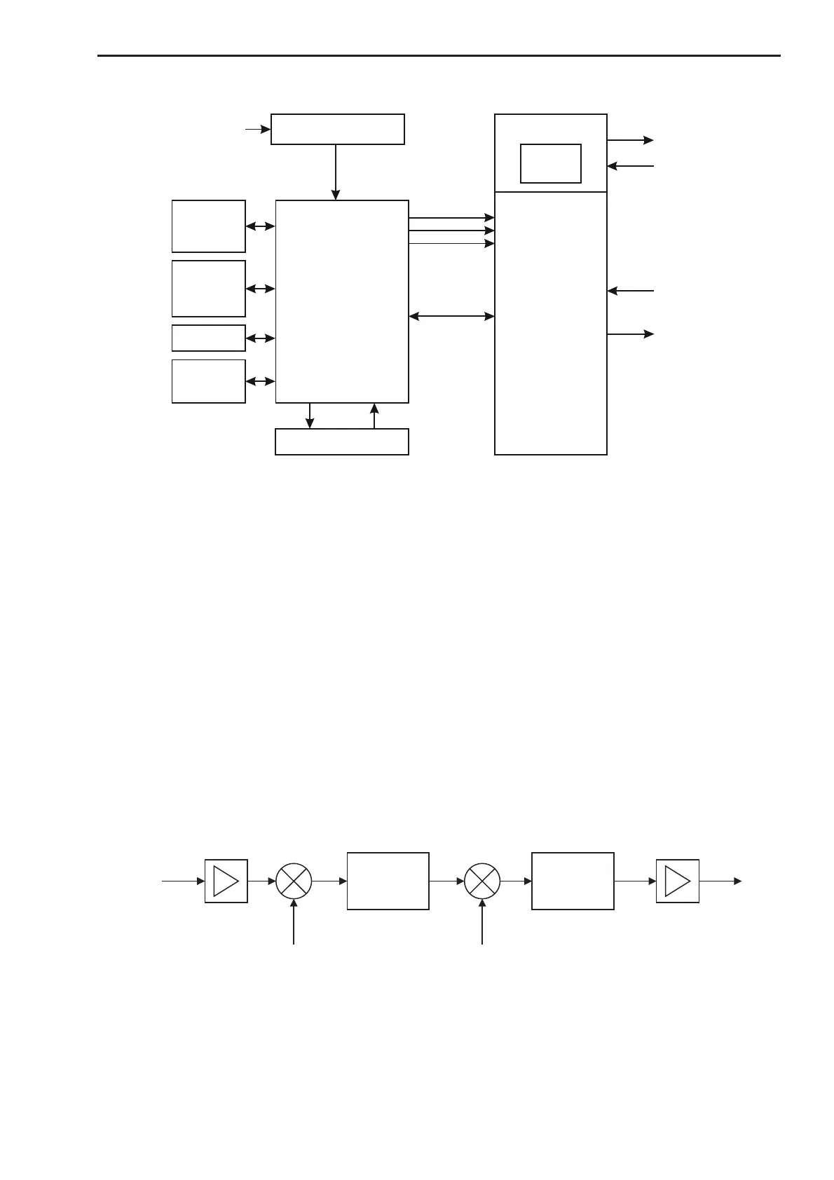
The input signal at 70 MHz, 140 MHz or 720 MHz passes first through an IF amplifier. This amplifier unit is
equipped with a gain variation of 30 dB with 0.1 dB step size. For compensation of transmission line charac-
teristics, an adjustable gain equalizer is integrated within the IF-amplifier.
The output signal of this amplifier is converted within the 1
st
mixer to a fixed IF frequency at typically
2.45 GHz (or 2.44 GHz). The local oscillator fixed LO feeds the mixer with the LO signal. At this IF frequency
a linear phase filter selects the correct mixer output signal. This filter has a very low group delay distortion.
In the 2
nd
mixer the IF signal at typically 2.45 GHz (or 2.44 GHz) is converted directly to the output band. The
microwave local oscillator MW LO feeds the mixer with a wide tunable LO signal. A multi-loop synthesizer
consisting of a coarse synthesizer and a fine step synthesizer generates the MW LO-signal. The reference for
this synthesizer is either an internal 10 MHz OCXO or an external 5 MHz or 10 MHz reference signal. The
step size of 100 Hz is at every MW LO Frequency an exact ratio of 10 MHz/10
5
.
The output signal is filtered by a microwave band pass filter and passes then through an output amplifier.
Figure 2: Upconverter module with double conversion, simplified block-diagram
In some cases (manly for devices with 720 MHz IF) single conversion is used. This is shown in the following
block-diagram:
 Loading...