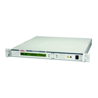
Figure 5: Front panel
1 – Status LED’s for TX On, Test Mode, Remote Status/Activity, Warnings, Stored Alarms, Alarms
2 – LCD Display in VSCU units, VFD Display in VHCU units
3 – Cursor keys
4 – Function keys
5 – Test outputs
6 – Power switch
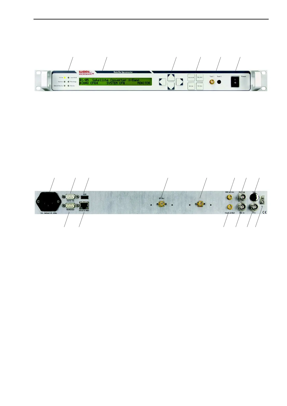
2.6 Rear Panel
Figure 6: Rear panel
1 – Power Supply AC Input 100 … 240V including mains fuses
2 – Alarm/mute interface
3 – USB 2.0 interface
4 – M&C remote control serial interface RS485/RS232
5 – M&C Ethernet interface (10/100 MBit)
6 – RF output
7 – RF output 2 (option)
8 – Test output for local oscillator (MW LO)
9 – Internal 10 MHz reference output
10 – Test output (option)
11 – Test output for local oscillator (fixed LO)
12 – Input for external reference (5 or 10 MHz)
13 – IF input
14 – GND connector
 Loading...