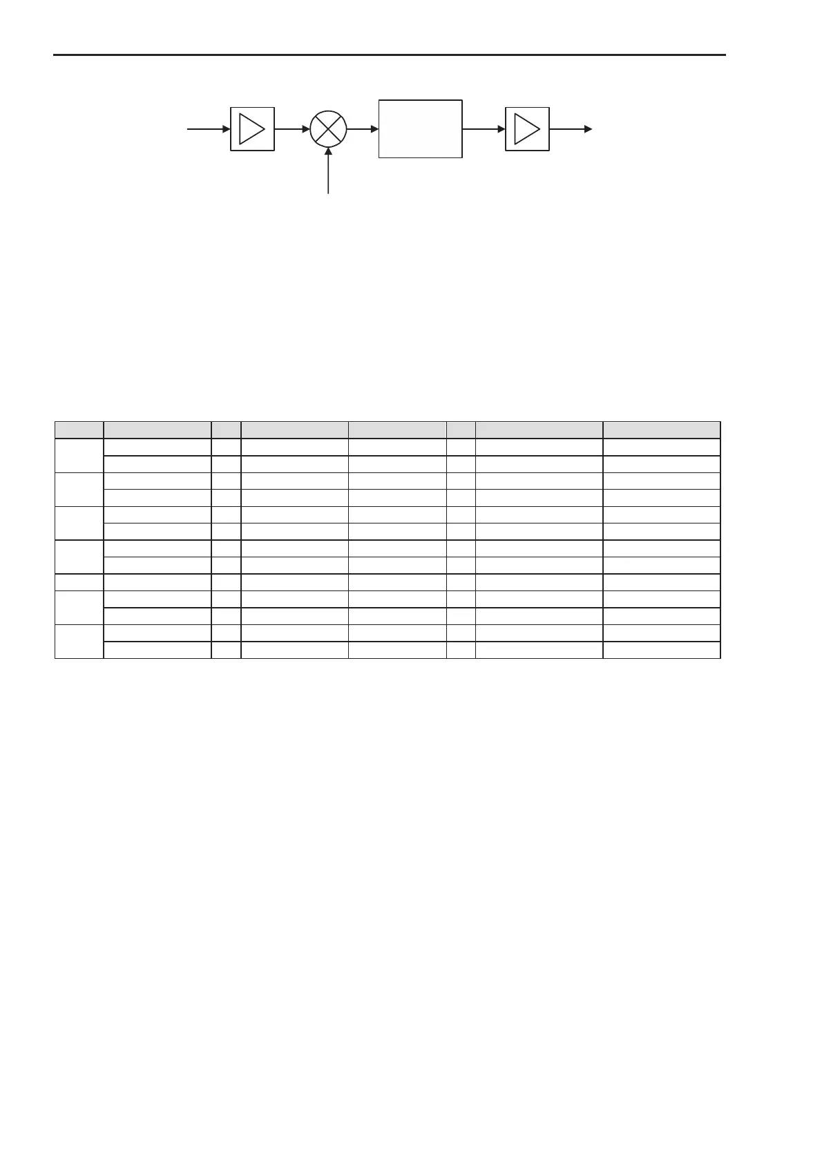
Figure 3: Upconverter module with single conversion, simplified block-diagram
2.3.3 Local Oscillators
Both local oscillators are built with PLL-Synthesizers. The synthesizers use an internal reference of 90 MHz.
This 90 MHz Reference is direct synthesized by multiplication of a 10 MHz OCXO. To synchronize multiple
converters in LO-phase it is also possible to phase-lock the internal 10 MHz OCXO to an external reference.
The frequency of this external reference can be either 5 MHz or 10 MHz.
Several frequencies and frequency ranges for the RF output signal, the LO signals and the IF input signals
are listed in Figure 4.
Figure 4: Frequencies and frequency ranges
2.3.4 Warm Up Period
When the converter is powered on, it takes some time to boot the firmware (approx. 1 minute). After booting
some time is required for the oven controlled crystal oscillator (OCXO) to warm up. Only after sufficient warm
up the specified maximum frequency offset is established. Therefore a warm up time is foreseen, during
which an oven cold warning is generated. The signal path is automatically switched off if the unit is in warm
up period. In this case the “TX On” LED is orange instead of green when the unit is configured for TX on.
2.4 Power Supply
The power supply has the following main parameters:
· Switched mode power supply for industrial application
· Standard Input voltage range is 90 V…264 V AC (50…60 Hz)
· Output Voltage: 24 V, max 2.0 A (Ta = 50 °C) / 1.2 A (Ta = 70 °C)
· Efficiency typical: > 86 %
· The power supply is protected against overload and short circuit operation.
· Recommended mains fuse: 3.15 A or 2 A (as indicated on unit).
 Loading...