Satellite Upconverter Manual WORK Microwave
15 / 49 V151207
2.7 Connectors on the Rear Panel
2.7.1 Mains AC Input Connector Block
The mains AC input connector block includes a male power input connector according to IEC/EN 60320. It
also includes two mains fuse (type 5 x 20 mm). The allowed ranges for the AC input voltage, the input fre-
quency are printed on the label near the connector block.
2.7.2 Alarm Interface
The alarm interface connector is located on the rear panel. The alarm interface has 2 alarm outputs and an
input for a “Hardware Mute” signal (RF-Inhibit). Two relay contacts are used for the alarm outputs.
The mute input signal is processed by the controller. This input is a 5 V TTL input with internal pull up. If mut-
ing via this input is enabled by software a low level (or connection to ground) enables the output of the con-
verter and a high level (or open input) disables the output of the converter.
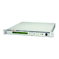
Important: When the “Hardware-Mute” is enabled by software or front panel setting, pin 4 and pin 9
must be connected for normal operation!
Figure 8: Internal connections of the Alarm Connector (SUB D9 female) in
normal operation (powered on, no alarm)
In case of alarms (excluding warnings) or when the Upconverter is switched off, pin 2 and pin 1 as well as
pin 7 and pin 3 are connected. In normal operation pin 2 and pin 6 as well as pin 7 and pin 8 are connected.
The maximum allowed current for the alarm contacts is 200 mA, the maximum allowed voltage is 42 V.
2.7.3 M&C USB Interface
The Full Speed USB 2.0 interface with a USB A connector can be used to exchange data files with the com-
munication controller, e.g. uploading firmware updates or saving the device configuration files. Typically a
USB memory stick can be connected.
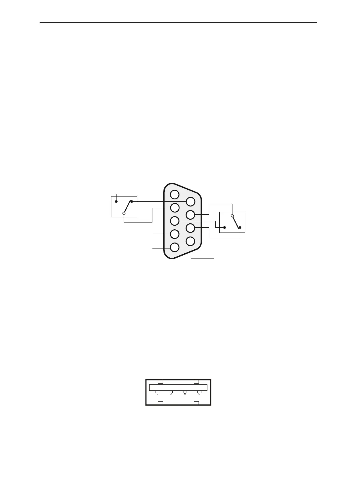
1 2 3 4
Figure 9: USB A Connector
 Loading...