Satellite Upconverter Manual WORK Microwave
19 / 49 V151207
3 Front Panel Operation
3.1 Power Switch
With the power switch on the front panel the mains supply for the Upconverter can be switched on or off. The
switch is recessed to achieve protection against unintentional operation.
3.2 Indicators
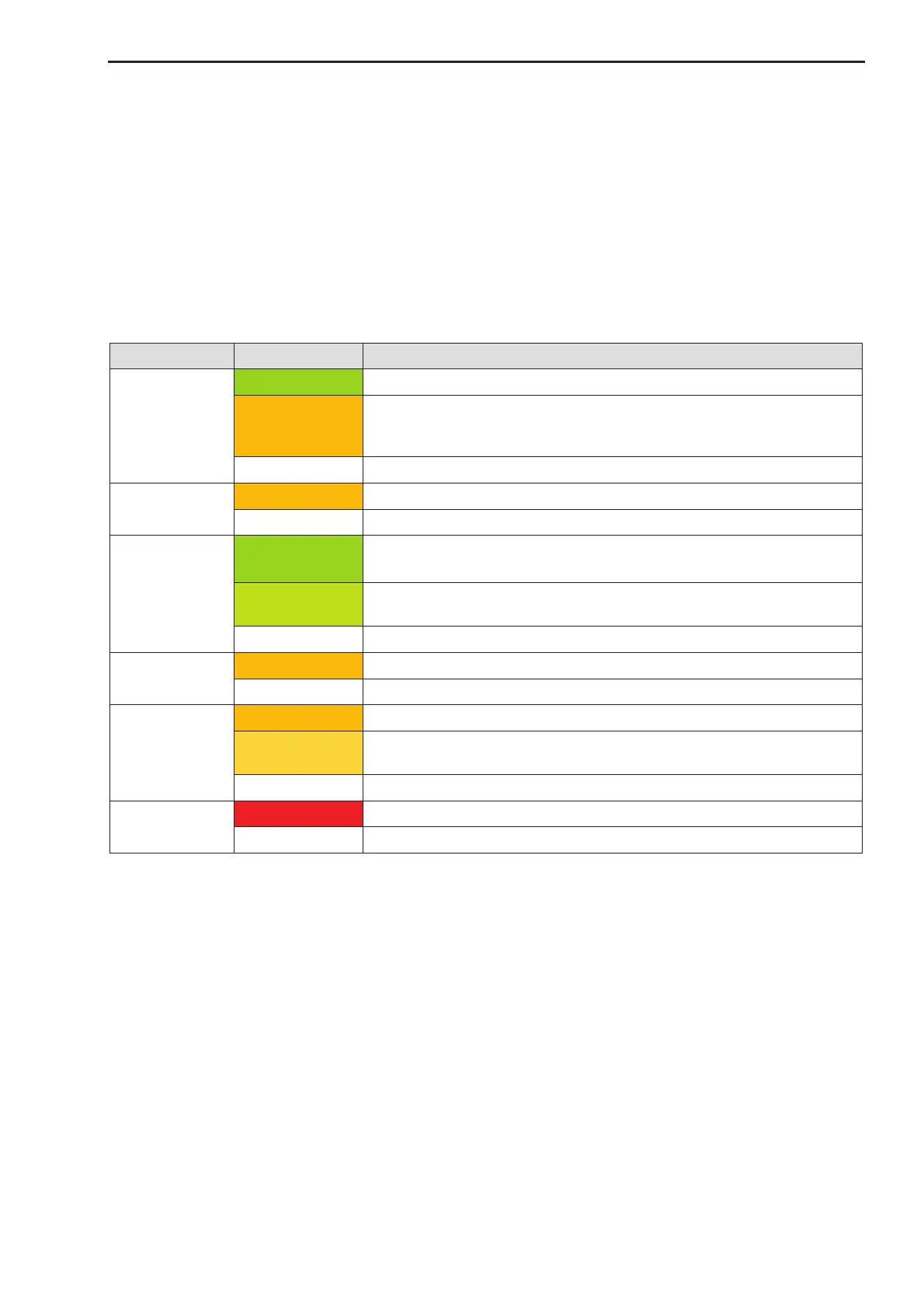
There are 6 LED’s on the front panel to indicate the operating conditions:
The signal path is enabled.
The signal path is commanded to be on, but is temporarily disabled by
a warning or alarm (e.g. warm up mute), and will automatically go to
enabled when the alarm or warning terminates
The signal path is disabled.
Unit is in remote mode (only available if REMOTE/LOCAL feature is
enabled) or lot of remote access happens.
A remote user is active on the unit.
No remote user is active.
A warning condition is active.
Alarm conditions have been stored with a time stamp
The alarm history storage is full; no further alarms can be stored.
No alarms have been stored
An alarm condition is active
Notes: The REMOTE/LOCAL feature can be enabled in the System CFG menu, see 3.5.3.11.
If Multipoint commands are received which do not match to the internal multipoint address or mul-
tipoint packet format these commands are not indicated by the remote LED.
3.3 Test Outputs
The two optional test outputs on the front panel allow monitoring of the RF output and (optional) the IF input
signal:
· Test 1: RF output monitor signal (standard)
· Test 2: IF input monitor signal (option)
All test outputs have an approx. 20 dB reduced power level compared to the main IF/RF signal on the rear
panel.
 Loading...