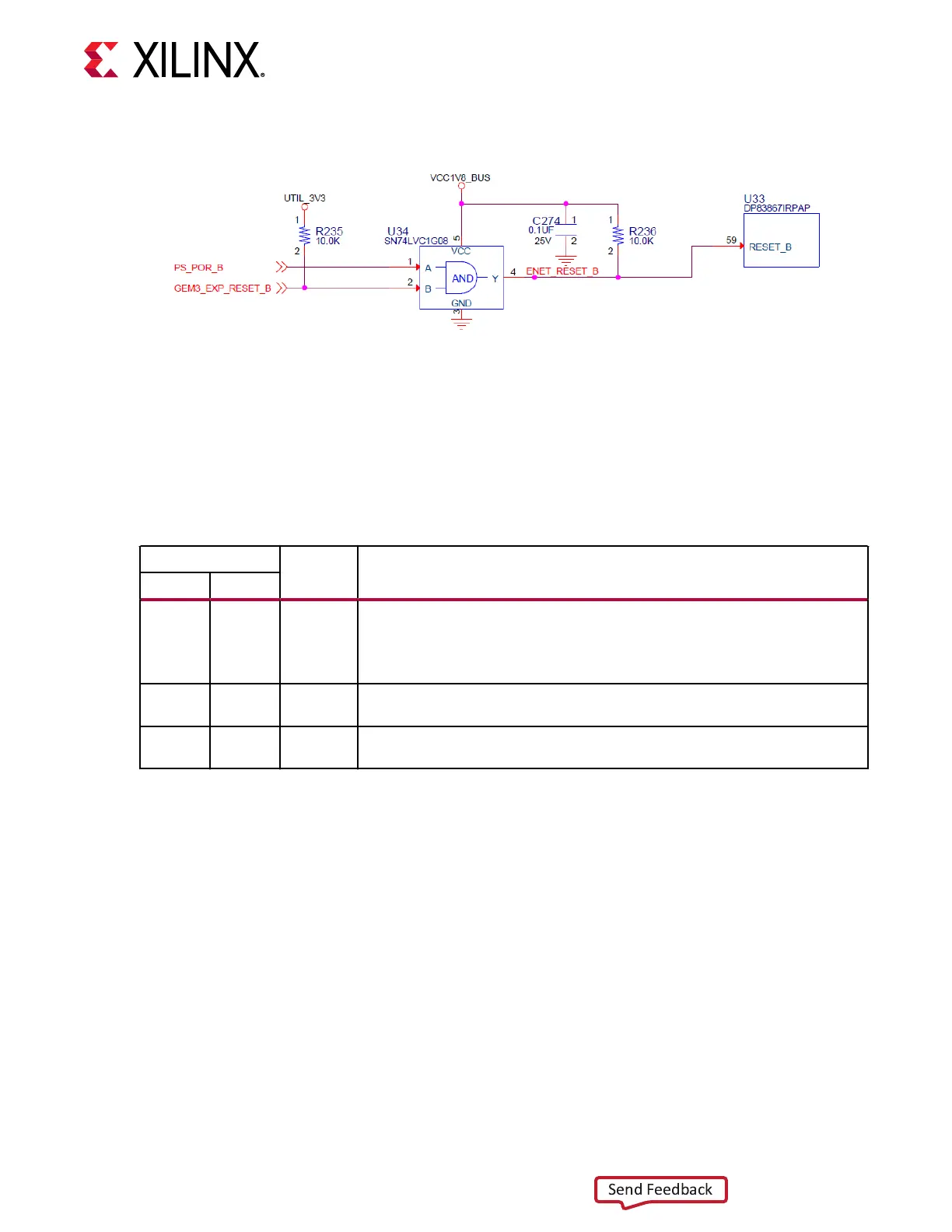
Figure 14: Ethernet PHY Reset Circuit
Ethernet PHY LED Interface
[Figure 2, callout 16]
The DP83867IRPAP PHY U33 LED interface (LED_0, LED_2) uses the two LEDs embedded in
the P1 RJ45 connector bezel. The LED funconal descripon is as shown in the following table.
Table 16: Ethernet PHY LED Functional Description
Pin
Type Description
Name Number
LED_2 61 S, I/O, PD
By default, this pin indicates receive or transmit activity.
Additional functionality is configurable by means of LEDCR1[11:8] register bits.
Note: This pin is a strap configuration pin for RGZ devices only.
LED_1 62 S, I/O, PD
By default, this pin indicates that 100BASE-T link is established.
Additional functionality is configurable by means of LEDCR1[7:4] register bits.
LED_0 63 S, I/O, PD
By default, this pin indicates that link is established.
Additional functionality is configurable by means of LEDCR1[3:0] register bits.
The LED funcons can be re-purposed with a LEDCR1 register write available through the PHYs
management data interface, MDIO/MDC. LED_2 is assigned to ACT (acvity indicator) and
LED_0 indicates link established.
LED_1 (100BASE-T link established) is a separate LED DS8 located on the top side of the board
near the RJ45 P1 connector (Figure 2, callout 16).
For more Ethernet PHY details, see the TI DS83867 data sheet on the Texas Instruments
website.
The detailed RFSoC connecons for the feature described in this secon are documented in the
ZCU208 board XDC le, referenced in Appendix B: Xilinx Design Constraints.
Chapter 3: Board Component Descriptions
UG1410 (v1.0) July 8, 2020 www.xilinx.com
ZCU208 Board User Guide 41

 Loading...


