The detailed RFSoC connecons for the feature described in this secon are documented in the
ZCU208 board XDC le, referenced in Appendix B: Xilinx Design Constraints.
GEM3 Ethernet (MIO 64-77)
[Figure 2, callout 16]
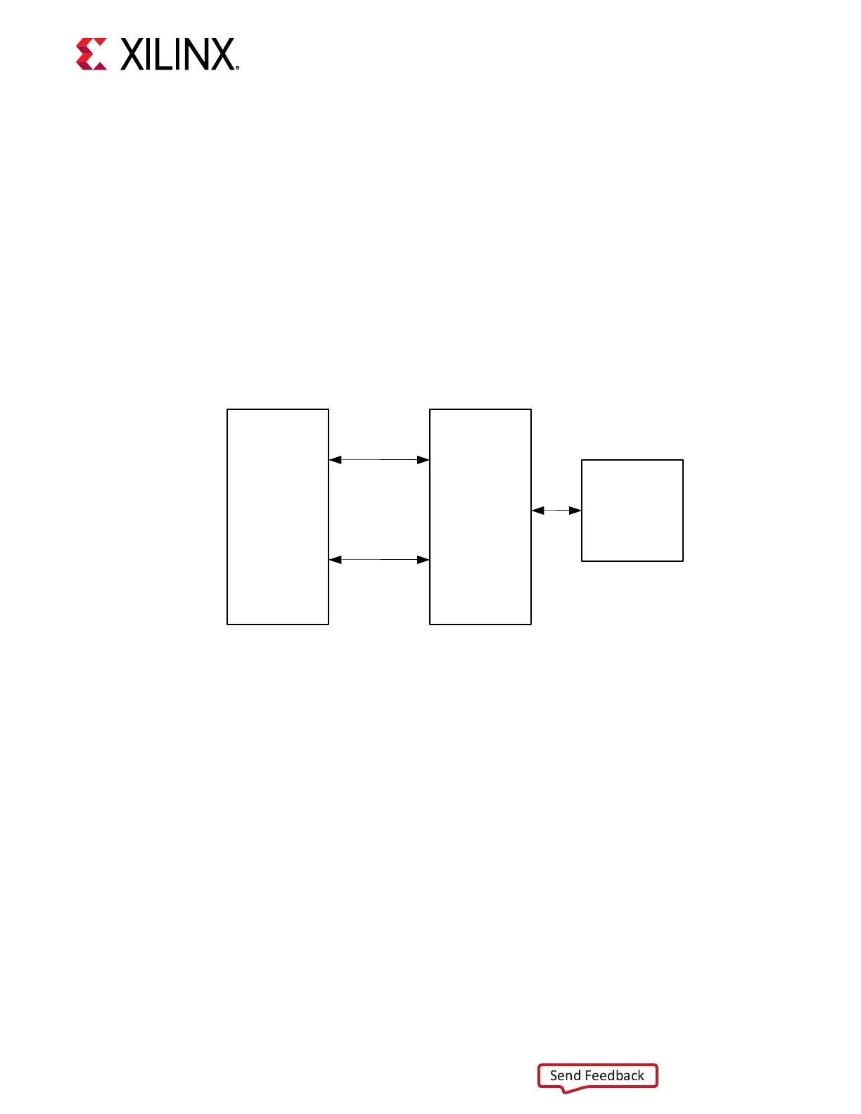
The PS-side Gigabit Ethernet MAC (GEM) implements a 10/100/1000 Mb/s Ethernet interface,
shown in the following gure, which connects to a TI DP83867IRPAP Ethernet RGMII PHY
before being routed to an RJ45 Ethernet connector. The RGMII Ethernet PHY is boot strapped to
PHY address 5'b01100 (0x0C) and Auto Negoaon set to Enable. Communicaon with the
device is covered in the TI DP83867 RGMII PHY data sheet on the Texas Instruments website.
Figure 13: Ethernet Block Diagram
TI
DP83867IR
GEM
MIO
RGMII
MDIO
RJ45 and
Magnetics
X23651-012220
10/100/1000 MHz Tri-Speed Ethernet PHY
[Figure 2, callout 16]
The ZCU208 board uses the TI DP83867IRPAP Ethernet RGMII PHY (U33) (see Texas
Instruments website) for Ethernet communicaons at 10 Mb/s, 100 Mb/s, or 1000 Mb/s. The
board supports RGMII mode only. The PHY connecon to a user-provided Ethernet cable is
through a Wurth 7499111221A RJ-45 connector (P1) with built-in magnecs.
Ethernet PHY Reset
The DP83867IRPAP PHY U33 reset circuit is shown in the following gure. The DP83867IRPAP
can be reset by the GEN3_EXP_RESET_B signal through the I2C0 TCA6416A U15 bus expander
P06 pin 10 or the PS_POR_B signal generated by the MAX16025 U6 POR device pin 11.
SW4 pushbuon at the MAX16025 U5 pin 6 input also triggers a PS_POR_B signal.
Chapter 3: Board Component Descriptions
UG1410 (v1.0) July 8, 2020 www.xilinx.com
ZCU208 Board User Guide 40

 Loading...


