iFT Series Hardware Installation Manual ADPRO
34 27817_05
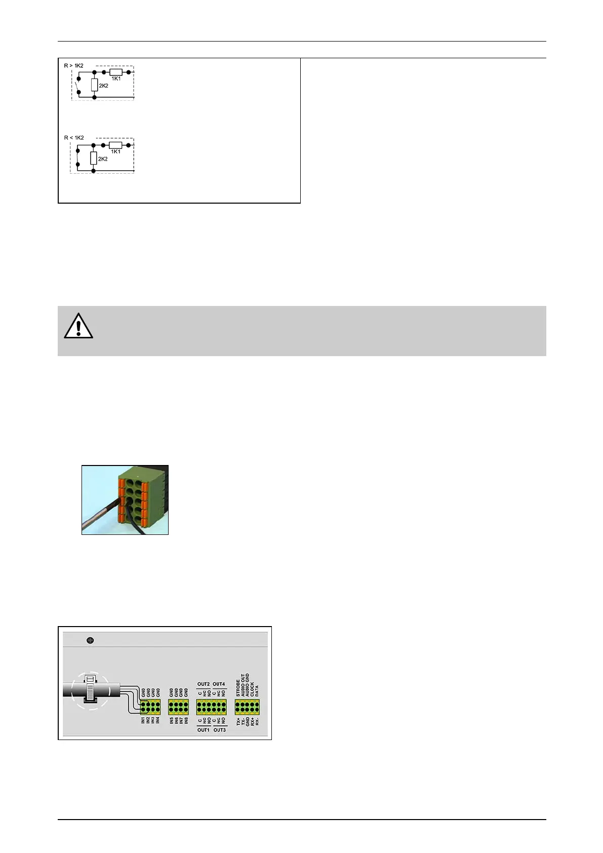
Normallyopen–DEOL
Shortcircuit=tamper
1K1=alarm
3K3=idle
Opencircuit=tamper
Normallyclosed–DEOL
Shortcircuit=tamper
1K1=idle
3K3=alarm
Opencircuit=tamper
(Defaultsetting)
7.4 Connecting Inputs and Outputs
Dependingonthetype,theMIOcardcanbeequippedwithDinkle(standard)orPhoenixspringinsertion
connectors.Forbothtypesyouneeda2mmslottedscrewdriver.
Warning!
Althoughthepicturebelowshowsonlytheconnector,itisstronglyrecommendedtoconnectthe
wireswiththeconnectorspluggedintothecard.Wiringahandheldconnectormaycauseinjuries.
WiringtoDinkleandPhoenixconnectorsisidentical,exceptthatthepositionoftabsandholesisswapped.The
pictureintheprocedurebelowshowsaPhoenixconnector.
Toconnectinputsandoutputs,proceedasfollows:
1. Pushtheslottedtabfirmlyinwardswiththescrewdriver.
2. Insertthestrippedwire(6–7mm)intothecorrespondingroundholeasdeeplyaspossible.
3. Releasethetabandpullthewiretocheckifitisproperlyfitted.
Wiregauge:
Solidandstranded:16–24AWG
(diam.1.3–0.5mm)
7.5 Cable Strain Relief
Afterconnectingallthewires,useatie-wraptoattachthecablestotheXOdevice’schassis.Runthetie-wrap
throughtheslotsinthechassisasshownbelow.Thetie-wrapservesasastrainreliefandmakessurethatthe
wiringstaysinplacewhenhandlingtheXOdevice.