VESDA ECO Detector by Xtralis
Do not install your ECO detector if there are any signs of shipping
Inform your distributor if there is any visible damage.
ECO Detector is correct as per design specifications for the
site. Refer to the Model number located on the main product
the gas types and ranges are of the correct specification.
Follow the steps below to fix the Detector to the pipe work
•
Before fitting the ECO unit to the pipe work, ensure that any glue used in
fixing the pipes has been given sufficient time to cure such that it any
vapours from the glue will not affect the gas detection.
• At the preferred location within the pipe
work, as determined by reference
to the previous section of this document, remove
the pipe. The exact length of pipe to be removed
work being used, but as a guide the lengths are
approximately
o 60 mm when installing in a 25mm OD pipe
o 4 inches (100 mm) when installing in a ¾” BPS
It is suggested that the pipe is cut to permit subsequent adjustment if
required, to maintain a good airtight fit.
• Ensure that the cuts on the pipe are perpendi
cular to the pipe and that
there are no burrs or sharp edges present. If so, trim
these.
• Verify correct orientation of ECO detector, that
the flow arrow on the side
is in the same direction as the sample airflow
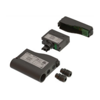
sert the detector into the open segment of the pipe, ensuring that the
pipe entry to the detector is square and the pipes sit correctly in the
to provide a sufficient air tight seal between them
• DO NOT GLUE THE PIPES TO THE DETECTOR.
and is an obstacle to future maintenance
•
If the gas test port is not to be permanently connected, ensure that the
blanking plug supplied with the unit is fitted firmly in place.
• Alternatively, if a permanent connection is to be made
use 6mm OD pipe to connect to the integrated pipe interface
is securely fitted and that it is closed at the opposite end during normal
operation.
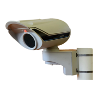
• When mounting the ECO detector, ensure that
device is oriented such th
the Status Indicators are visible for inspection purposes.
Do not install your ECO detector if there are any signs of shipping
Inform your distributor if there is any visible damage.
ECO Detector is correct as per design specifications for the
Before fitting the ECO unit to the pipe work, ensure that any glue used in
fixing the pipes has been given sufficient time to cure such that it any
work, as determined by reference
work being used, but as a guide the lengths are
It is suggested that the pipe is cut to permit subsequent adjustment if
cular to the pipe and that
the flow arrow on the side
is in the same direction as the sample airflow
sert the detector into the open segment of the pipe, ensuring that the
pipe entry to the detector is square and the pipes sit correctly in the
to provide a sufficient air tight seal between them
If the gas test port is not to be permanently connected, ensure that the
blanking plug supplied with the unit is fitted firmly in place.
use 6mm OD pipe to connect to the integrated pipe interface
is securely fitted and that it is closed at the opposite end during normal
device is oriented such th