VESDA ECO Detector by Xtralis Product Guide
17898_05 Configuration 45
of the Address is “1”. For more information on Modbus addresses please refer to
the Modbus Interface
Air Flow Tab
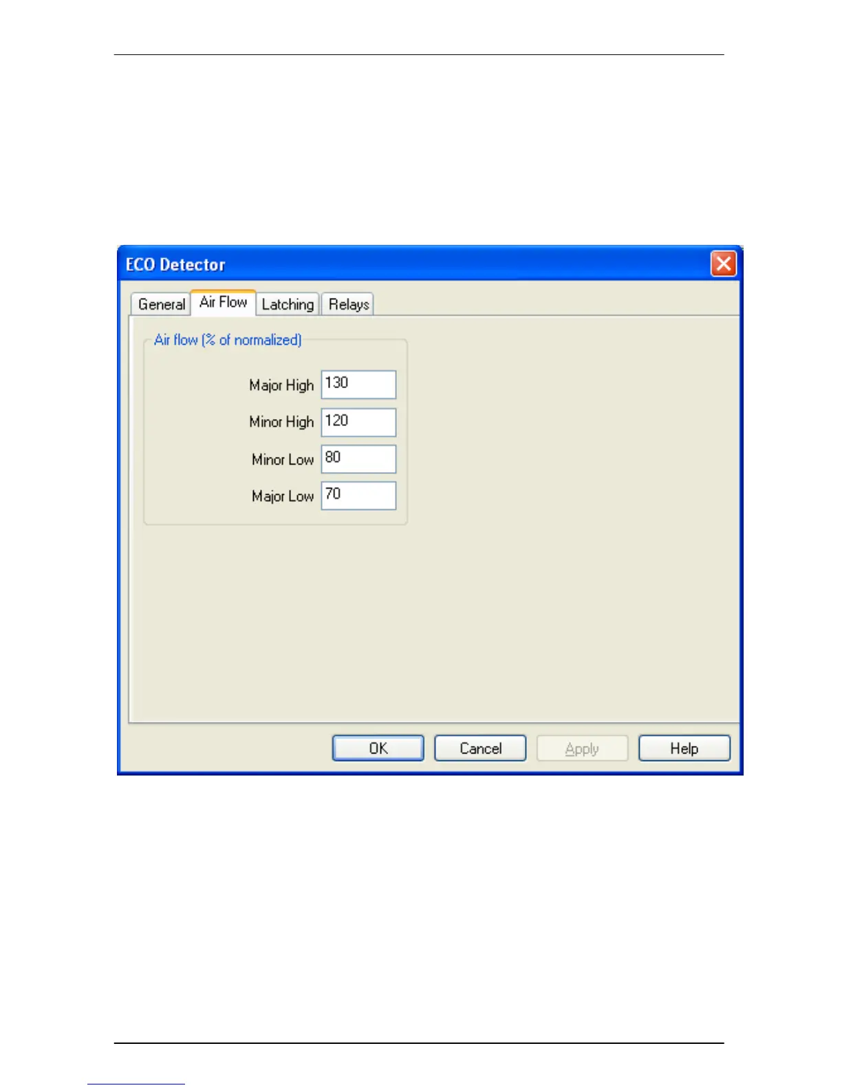
The ‘Air Flow’ tab, shown in Figure 28, is used to specify the thresholds for the Air
Flow fault conditions.
Figure 28 ECO Detector, Air Flow Tab
When the configured thresholds are exceeded, Flow faults will be raised. From the
factory, the default settings for the Airflow faults are as indicated in the figure above.
To perform Flow Normalization please refer to page 48. Flow Normalization