VESDA ECO Detector by Xtralis Product Guide
17898_05 vii
Contents
Overview .................................................................................................................. 1
Introduction to the VESDA ECO .................................................................... 1
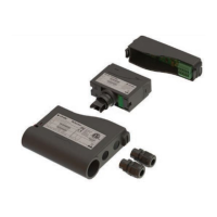
Packing Contents .......................................................................................... 1
Product Overview .......................................................................................... 2
Operation ....................................................................................................... 3
Key Features ................................................................................................. 4
Detector Location ................................................................................................... 5
Installation ............................................................................................................... 7
Air Inlet/Outlet Pipe Connections ................................................................... 7
Mechanical Dimensions ................................................................................. 7
Mechanical Installation .................................................................................. 9
Electrical Installation .................................................................................... 11
Cable Specification ....................................................................... 13
Power Supply Connection ............................................................. 14
RS485 Interface Connection ......................................................... 15
Relay Connections ........................................................................ 18
4-20mA Current Sources .............................................................. 21
Digital Input Connection ................................................................ 23
Principles of Operation ........................................................................................ 24
Before You Begin ........................................................................................ 24
Status Indicator Operation ........................................................................... 25
Serial Communication Interfaces ................................................................. 25
Modbus Interface .......................................................................... 26
USB Configuration ........................................................................ 26
Relay Contacts ............................................................................................ 27
Event Logging.............................................................................................. 28
Event Log Retrieval ....................................................................... 28
Removal of Memory Card ............................................................. 28
Current Outputs ........................................................................................... 29
Fault Conditions ............................................................................ 29
Gas Calibration Conditions ........................................................... 29
Alarms ......................................................................................................... 30
Alarm Threshold Configuration ..................................................... 30
Alarm Reset .................................................................................. 30
Configuration storage .................................................................................. 30
Calibration ................................................................................................... 31
Configuration ........................................................................................................ 33
VSC Connection Configuration ..................................................... 33