Product Guide VESDA ECO Detector by Xtralis
12 Installation 17898_05
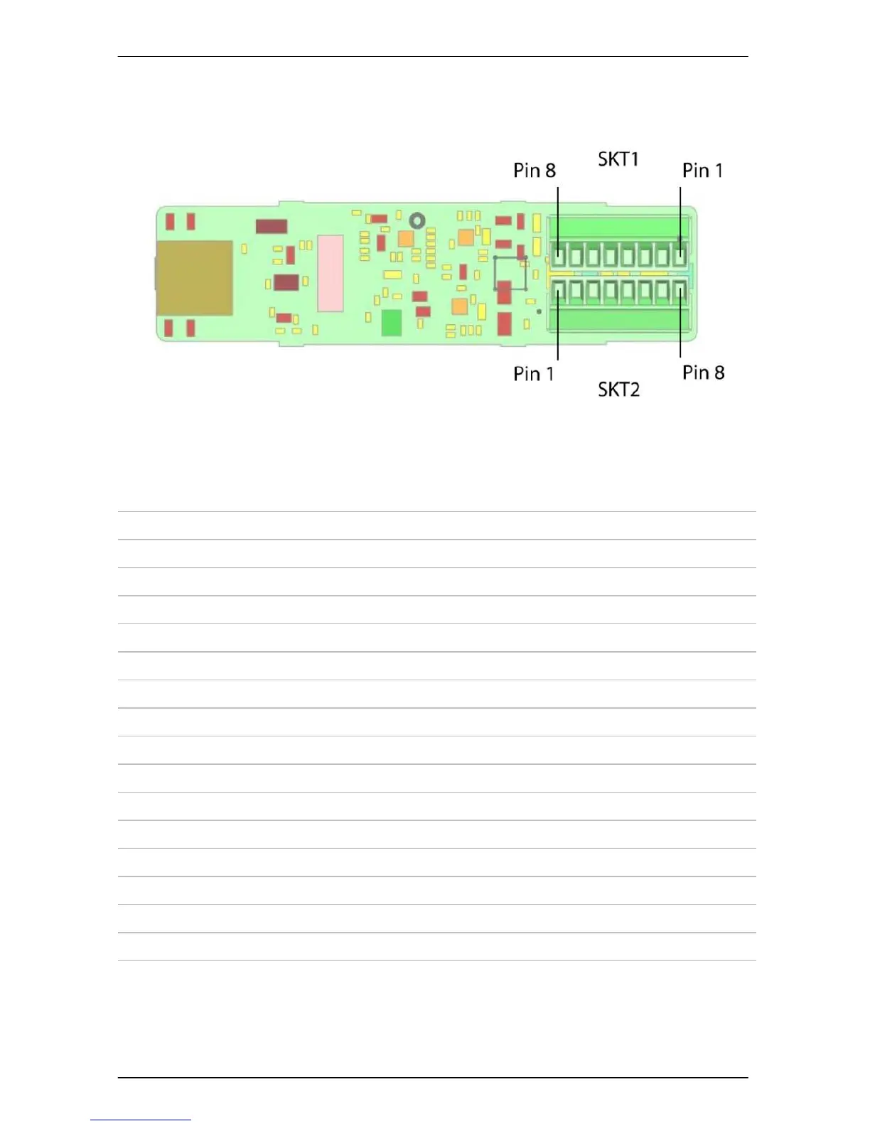
Upon removing the lid, the two 8 way connection terminals are exposed. The pin
numbering of these connections is indicated in Figure 5 below.
Figure 5. Detector Internal Connector Terminal Allocations
The electrical functions of the terminals are as follows
SKT1 Pin 1 Relay 1, Normally Closed, Volt Free Contact
SKT1 Pin 2 Relay 1, Normally Closed, Volt Free Contact
SKT1 Pin 3 Relay 2, Normally Closed, Volt Free Contact
SKT1 Pin 4 Relay 2, Normally Closed, Volt Free Contact
SKT1 Pin 5 Relay 3, Normally Closed, Volt Free Contact
SKT1 Pin 6 Relay 3, Normally Closed, Volt Free Contact
SKT1 Pin 7 Relay 4, Normally Open, Volt Free Contact
SKT1 Pin 8 Relay 4, Normally Open, Volt Free Contact
Note . “Normally” above refers to the state when the ECO is unpowered.
SKT2 Pin 1 RS485 Signal A ( Modbus D0 )
SKT2 Pin 2 RS485 Signal B ( Modbus D1 )
SKT2 Pin 3 Power Supply Input (Nominally +24V)
SKT2 Pin 4 Power Supply return
SKT2 Pin 5 Cable Screen Termination
SKT2 Pin 6 Digital Input/Open Collector Output
SKT2 Pin 7 4-20mA Current Output source A
SKT2 Pin 8 4-20mA Current Output source B
The specific details of the connection to each function is detailed in the following
sections
 Loading...