VESDA VLI Product Guide VESDA by Xtralis
6 www.xtralis.com
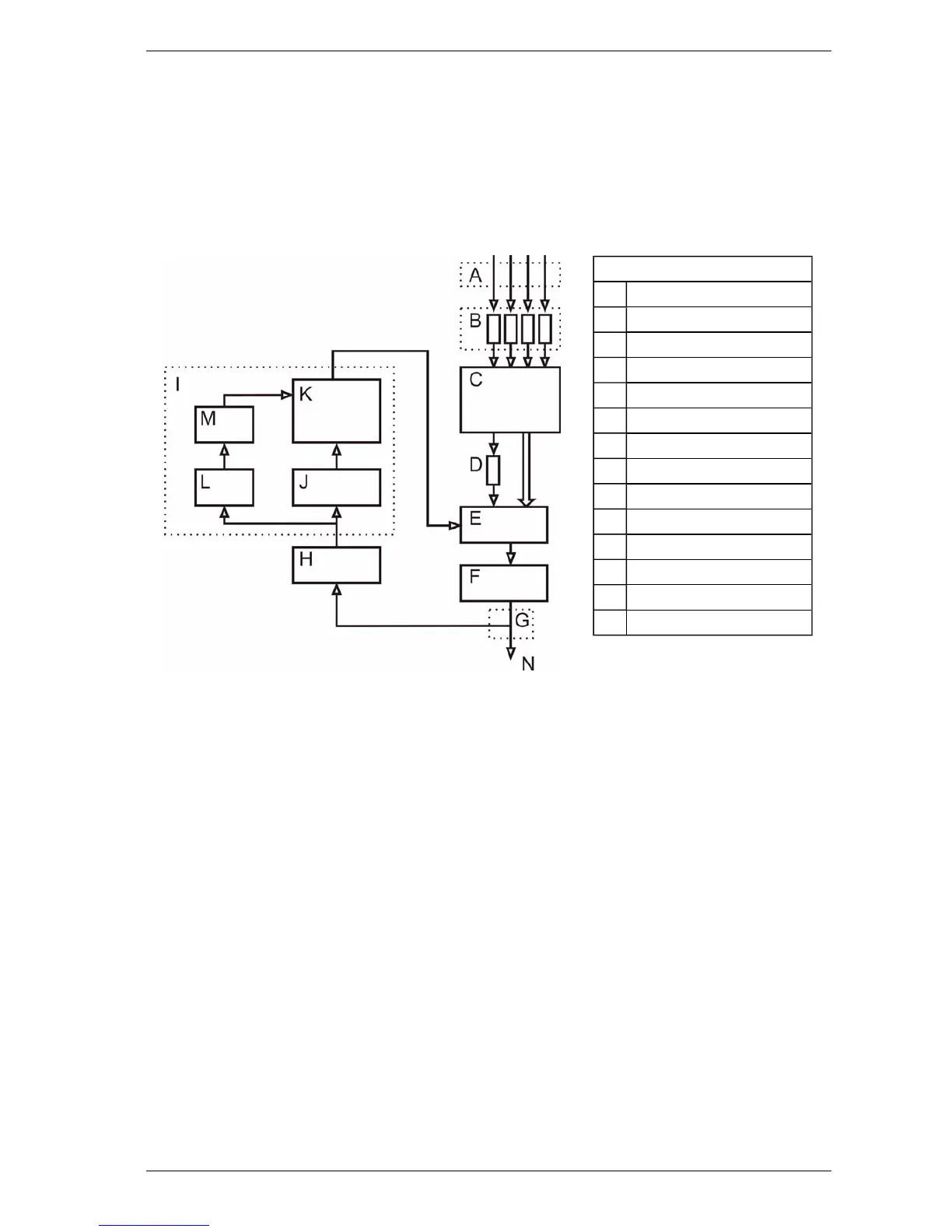
2.2 How the VLI works
The VLI detector continually samples air from a protected area via a sampling pipe network (A).
Upon entering the detector, the air passes four ultrasonic flow sensors (B), then through the mixer
compartment of the Intelligent Filter (C), where it is split between two pathways. One pathway
carries the majority of the air through the HEPAfilter compartment, while the other carries a small
proportion of the air through a separate ultrasonic flow sensor (D). The air recombines in the main
aspirator (F).
Legend
A Pipe Inlets
B Ultrasonic Flow Sensors
C Intelligent Filter
D Ultrasonic Flow Sensor
E Manifold
F Main Aspirator
G Sampling Probe
H Secondary Foam Filter
I Chamber Assembly
J Chamber Flow Sensor
K Chamber
L Tertiary Clean Air Filter
M Auto Zero Aspirator
N Exhaust
Figure 2-2: Internal airflow example
Note: The Intelligent Filter is constantly monitored for blockage using the ultrasonic flow sensor in
the unfiltered path (D). The arrangement of four sets of ultrasonic flow sensors at the
detector air inlets (A) and a separate ultrasonic flow sensor in the unfiltered path (D) allows
the detector to measure the split of the airflow ratio as the filter load increases over time.
The detector sets the sensitivity proportionally depending on flow ratio, thus ensuring
consistent and reliable operation over time.
A portion of recombined air sample is then passed through a sampling probe (inertial separator) and
the secondary foam filter (H)which ensures only smoke sized particles are passed into the detection
chamber for analysis. The larger dust particles are unable pass through the probe and filter
arrangement and hence are exhausted out of the detector (N). This eliminates nuisance alarms
caused by larger dust particles and extends the life of the chamber (K). The tertiary clean air filter (L)
provides air to form clean air barriers within the chamber (K), which protects the optical surfaces
from contamination.
When smoke passes through the Chamber (K), it creates light scatter which is detected by the
sensor circuitry. The air sample is measured, and the detector reports smoke levels adjusted
according to the sensitivity ratio determined by the Flow Sensors (B and D). Air is exhausted from
the detector and may be vented back into the protected area (N).
Note: The status of the detector, all alarms, service and fault events, are monitored and logged
with time and date stamps. Status reporting can be transmitted via relay outputs, across
VESDAnet (VN version only) or BACnet.