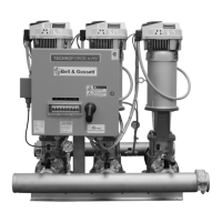
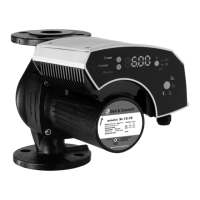
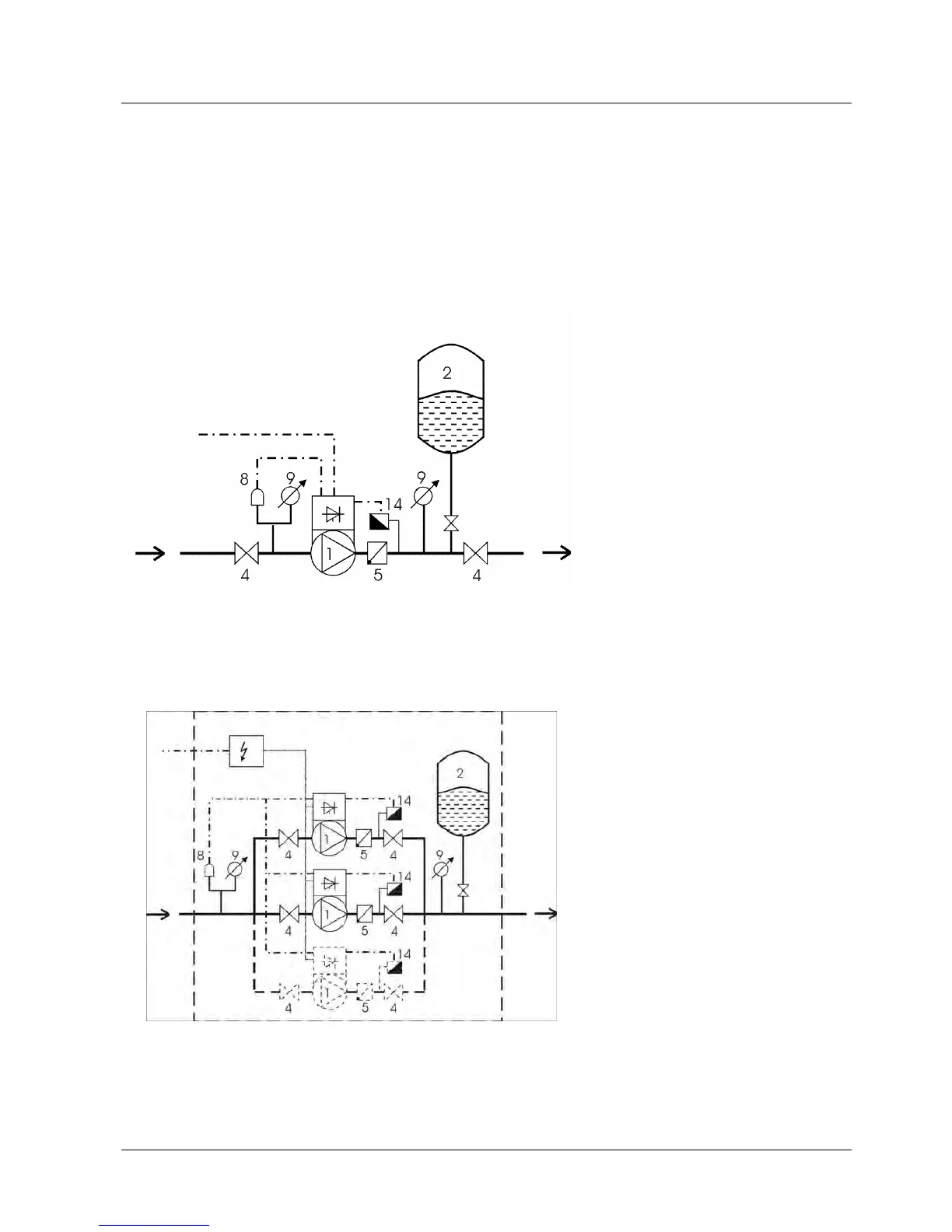
EasyManuals Logo

Xylem hydrovar hv 1.1 User Manual

Xylem hydrovar hv 1.1
60 pages
To Next Page IconTo Next Page
To Previous Page IconTo Previous Page
Page #7 background imageLoading...
Page #7 background image
7
2 System Design
The following diagrams show typical single pump and multi-pump systems using the
Hydrovar control unit. Connection can be made directly to a water supply or water
can be drawn from a break tank or well. In the case of break tanks and wells, level
switches, should be used to shut down the pumps when water is low. In the direct
connection, a pressure switch on the suction side should be used.
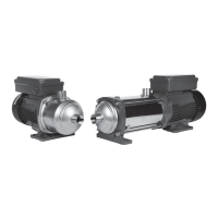
Single pump layout
Multiple pump Layout
(1) pump with drive head
(2) diaphragm tank
(3) distribution panel
(4) gate valves
(5) non return valves
(8) incoming pressure switch
(9) pressure gauges
(14) pressure transmitter

Table of Contents

Questions and Answers:

Question and Answer IconNeed help?

Do you have a question about the Xylem hydrovar hv 1.1 and is the answer not in the manual?

Xylem hydrovar hv 1.1 Specifications

General IconGeneral
BrandXylem
Modelhydrovar hv 1.1
CategoryWater Pump
LanguageEnglish

Related product manuals