Page 100 FT-950 OPERATING MANUAL
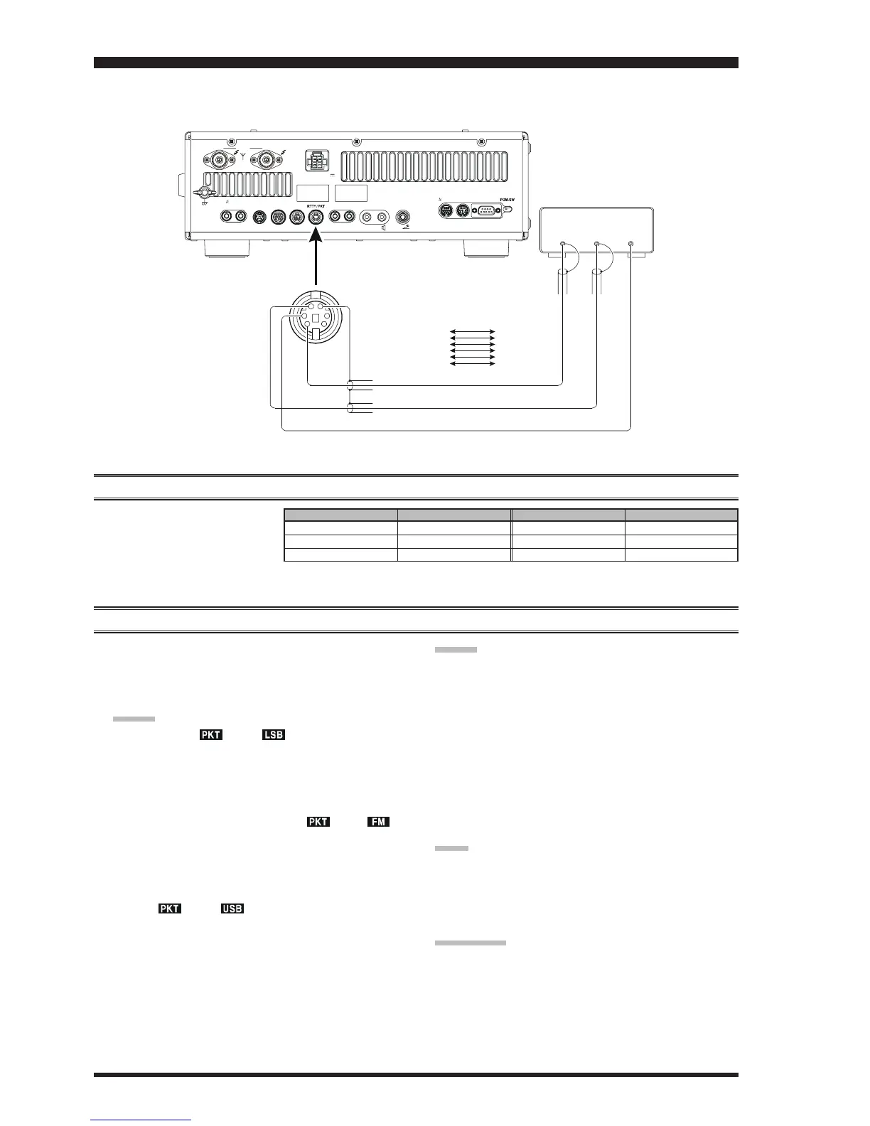
Packet operation is easily accomplished on the FT-950 by connecting your TNC (Terminal Node Controller) to the trans-
ceiver, per the illustration. “Packet” operation also applies to SSB-based AFSK data modes, such as PSK31, etc.
PACKET OPERATION
PACKET SETUP
(
INCLUDING SUBCARRIER FREQUENCY
)
Before operation can commence,
some basic setup procedures must
be performed using the Menu, to
configure your radio for the data
mode to be used.
BASIC SETUP
1. Press the
[
RTTY/PKT
]
button, briefly, to toggle the
selected Packet mode. Press the
[
RTTY/PKT
]
button
to toggle the mode between “
PKT-LSBPKT-LSB
PKT-LSBPKT-LSB
PKT-LSB” and “
RTTY-RTTY-
RTTY-RTTY-
RTTY-
LSBLSB
LSBLSB
LSB”.
ADVICE:
When both “ ” and “ ” icons appear on the
display, the mode is LSB SSB-based Data opera-
tion which is generally used for HF operation.
If you need to do FM-based 1200-baud packet on
the 29/50 MHz bands, press and hold in the
[
RTTY/
PKT
]
button repeatedly until the “ ” and “ ”
icons appear on the display, to engage the “PKT-
FM” mode.
To operate USB SSB-based Data modes, press and
hold in the
[
RTTY/PKT
]
button repeatedly until
the “ ” and “ ” icons are shown on the dis-
play, the FT-950 is configured for Packet opera-
tion in the “USB” mode.
2. When the “transmit” command is received from the
TNC, the transmitter of the FT-950 will automatically
be engaged. Likewise, the command to return to re-
ceive will cause the radio to revert to the receive mode.
ADVICE:
If you need to adjust the output level from the “DATA
OUT” pin (pin 5) of the RTTY/PKT jack on the rear
panel of the transceiver, please use Menu item “
051051
051051
051
DATA OUT LVLDATA OUT LVL
DATA OUT LVLDATA OUT LVL
DATA OUT LVL”. For the input level from the TNC, as
applied to the DATA IN pin (pin 1) of the RTTY/PKT
jack, please use Menu item “
050 DATA DT GAIN050 DATA DT GAIN
050 DATA DT GAIN050 DATA DT GAIN
050 DATA DT GAIN”.
During Packet operation via the rear panel’s RTTY/
PKT jack, the front panel MIC jack is cut off, so you
won’t have a “live microphone” problem during data
operation.
NOTE:
If you anticipate making data transmissions of longer than
a few minutes, we recommend that you reduce the trans-
mitter power to 1/3 ~ 1/2 of its normal maximum via the
Menu item “
111 TGEN TX PWR111 TGEN TX PWR
111 TGEN TX PWR111 TGEN TX PWR
111 TGEN TX PWR”.
QUICK POINT:
RTTY/PKT Jack Specifications
DATA IN (Pin 1)
Nominal Input Level: 50 mVp-p
Impedance: 10 k-Ohms
DATA OUT (Pin 5)
Maximum Output Level: 100 mVp-p
Impedance: 10 k-Ohms
MENU ITEM AVAILABLE VALUES
050 DATA DT GAIN 0 ~ 100
051 DATA OUT LVL 0 ~ 100
052 DATA VOX DLY 30 ~ 1000
(
ms
)
MENU ITEM AVAILABLE VALUES
053 DATA V GAIN 0 ~ 100
054 DADA PKTDISP –3000 ~ +3000
(
Hz
)
055 DATA PKT SFT –3000 ~ +3000
(
Hz
)
TO
1
ANT
DC IN
2
FROM
GND
ROT LINEAR TUNER PTT REC REM KEY
DMU CAT
EXT
SPKR
INPUT: DC 13.8 V
22 A
-TUNE
-TUNE
DATA
OUT
PTT
DATA
IN
D
A
T
A
I
N
D
A
T
A
O
U
T
D
A
T
A
P
T
T
G
N
D
RTTY/PKT JACK TNC
Pin 1
(
DATA IN
)
Pin 2
Pin 3
Pin 5
Pin 6
(
GND
)
(DATA
PTT
)
Pin 4 (FSK)
(
DATA OUT
)
(SQL OUT)
DATA OUT
GND
PTT
(No Connection)
DATA IN
(SQL Control)
 Loading...