Page 51FT-950 OPERATING MANUAL
INTERFERENCE REJECTION
IF NOTCH FILTER OPERATION
(
SSB/CW/RTTY/PKT/AM MODES
)
The IF NOTCH filter is a highly effective system that allows you to slice out an interfering beat note or other carrier signal
from inside the receiver passband.
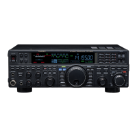
1. Press the
[
NOTCH
]
button to activate the Notch filter.
The LED inside the
[
NOTCH
]
button glows orange
and the current “null” position of the NOTCH filter
will appear in the NOTCH indicator on the display.
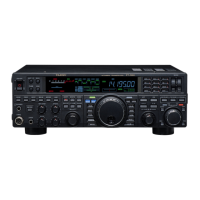
The
[
SELECT
]
knob functions as the Notch adjust-
ment knob.
2. Rotate the
[
SELECT
]
knob to adjust the “null” posi-
tion of the Notch filter.
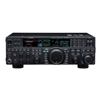
3. Press the
[
CLEAR
]
button to move the “null” position
to center.
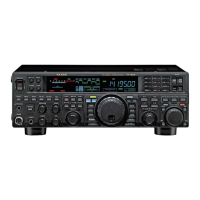
4. To cancel the NOTCH filter, press the
[
SELECT
]
knob
momentarily. The graphic disappears from the NOTCH
indicator on the display, confirming that the NOTCH
filter is no longer operation.
ADVICE:
Press the
[
SELECT
]
knob (momentarily) once more,
the NOTCH filter is activated again.
ADVICE:
The IF NOTCH Filter selection will be memorized
independently on each VFO stack of VFO-A and VFO-
B.
When the optional DMU-2000 Data Management Unit
is connected, the effect of the IF NOTCH filter may be
observed on the Audio Scope (on the “Oscilloscope”
page). The Notch will be observed as a “dip” in the
noise platform observed. What’s more, the “Waterfall”
display may be used to observe the effect of the IF
NOTCH filter, which will appear as a white area in the
colored background area.
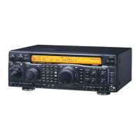
[
NOTCH
]
Button
[
SELECT
]
Knob
NOTCH Indicator
[
CLEAR
]
Button
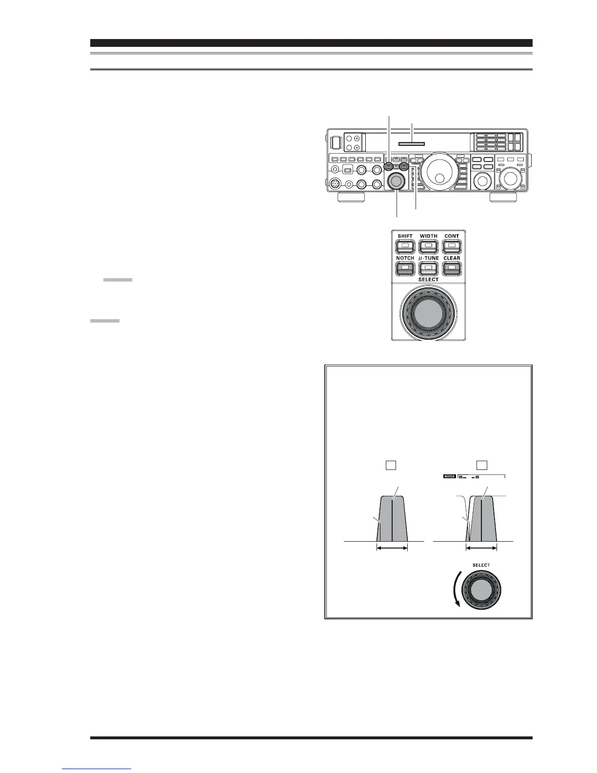
The performance of the IF NOTCH filter is shown
in Figure “A”, where the effect of rotation of the
[
SELECT
(
NOTCH
)]
knob is depicted. In Figure
“B” you can see the notching effect of the IF
NOTCH filter as you rotate the
[
SELECT
(
NOTCH
)]
knob to eliminate the incom-
ing interference.
IF
BANDWIDTH
QRM
(Heterodyne)
QRM
(Heterodyne)
IF
BANDWIDTH
Desired Signal Desired Signal
AB