22 Chapter 3—Touring the 01V
01V—Owner’s Manual
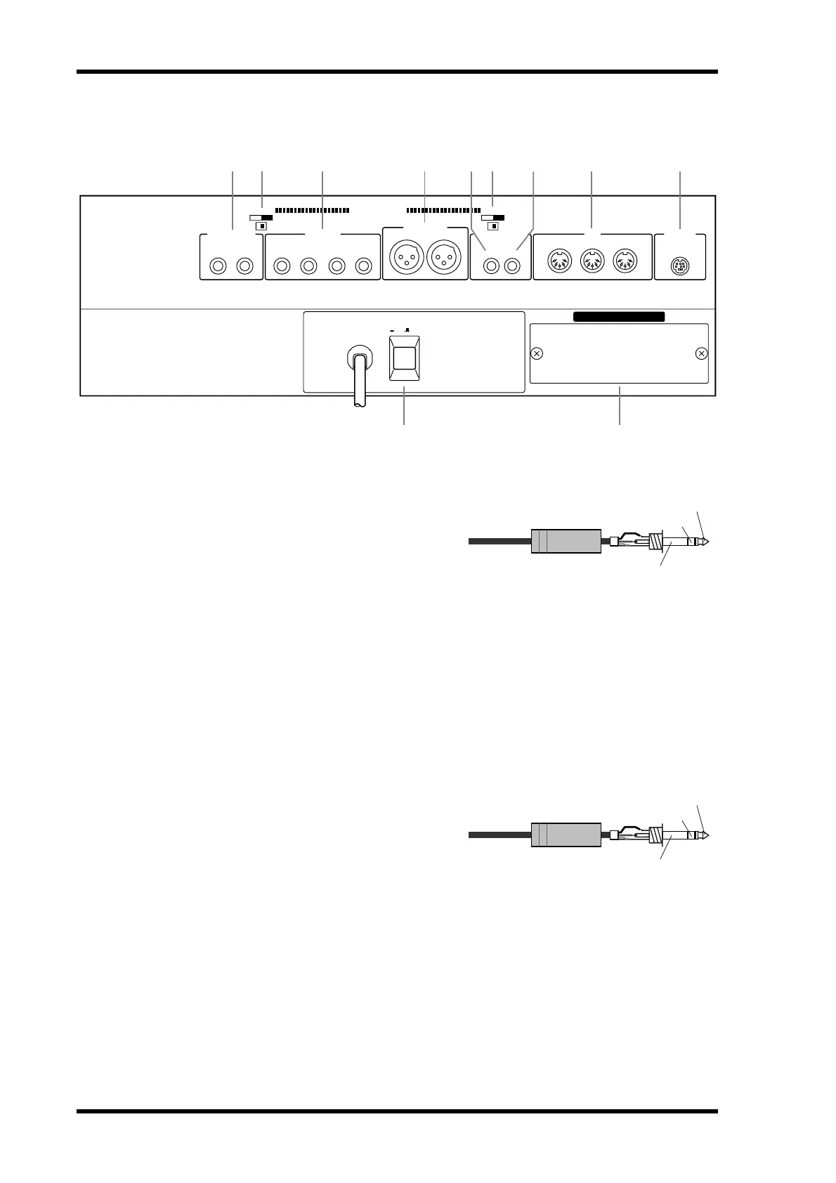
Rear Panel
A MONITOR OUT
These are balanced 1/4-inch phone jacks
with a +4 dB nominal output level. Bal-
anced or unbalanced phone plugs can be
connected. They output the monitor sig-
nals and should be connected to the inputs
on a monitor amplifier. The monitor signal
source is set using the MONITOR–2TR IN
switch and SETUP page 2, and the output
level is set using the MONITOR LEVEL
control.
B PHANTOM +48V ON–OFF Switches
The CH 1–6 and CH 7–12 PHANTOM +48V ON–OFF switches are used to turn on
and off the +48 V phantom power for XLR inputs 1 through 6 and 7 through 12,
respectively.
C OMNI OUTs
These are balanced 1/4-inch phone jacks
with a +4 dB nominal output level. Bal-
anced or unbalanced phone plugs can be
connected. These outputs can be config-
ured individually as analog bus outs, aux
sends, stereo outs, or direct outs for input
channels 1 through 16. Bus outputs are typ-
ically connected to multitrack recorders,
while aux sends are typically used to feed
external effects processors, foldback ampli-
fiers, and so on.
OPTION I/O
TO HOSTMIDIDIGITAL STEREO
STEREO OUT
PHANTOM +48V
OMNI OUT
POWER
MONITOR OUT
CH 7-12
+4dB (BAL)
RL
THRU
OUT IN
COAXIAL
OUT IN
+4dB (BAL)+4dB (BAL)
34LR21
ON
CH 1-6
ON/ OFF
OFF ON OFF
1 2 3 4 2 65 7 8
9 J
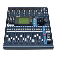
1/4" TRS phone plug
Tip (hot)
Ring (cold)
Sleeve (ground)
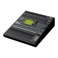
1/4" TRS phone plug
Tip (hot)
Ring (cold)
Sleeve (ground)