20 Chapter 3—Touring the 01V
01V—Owner’s Manual
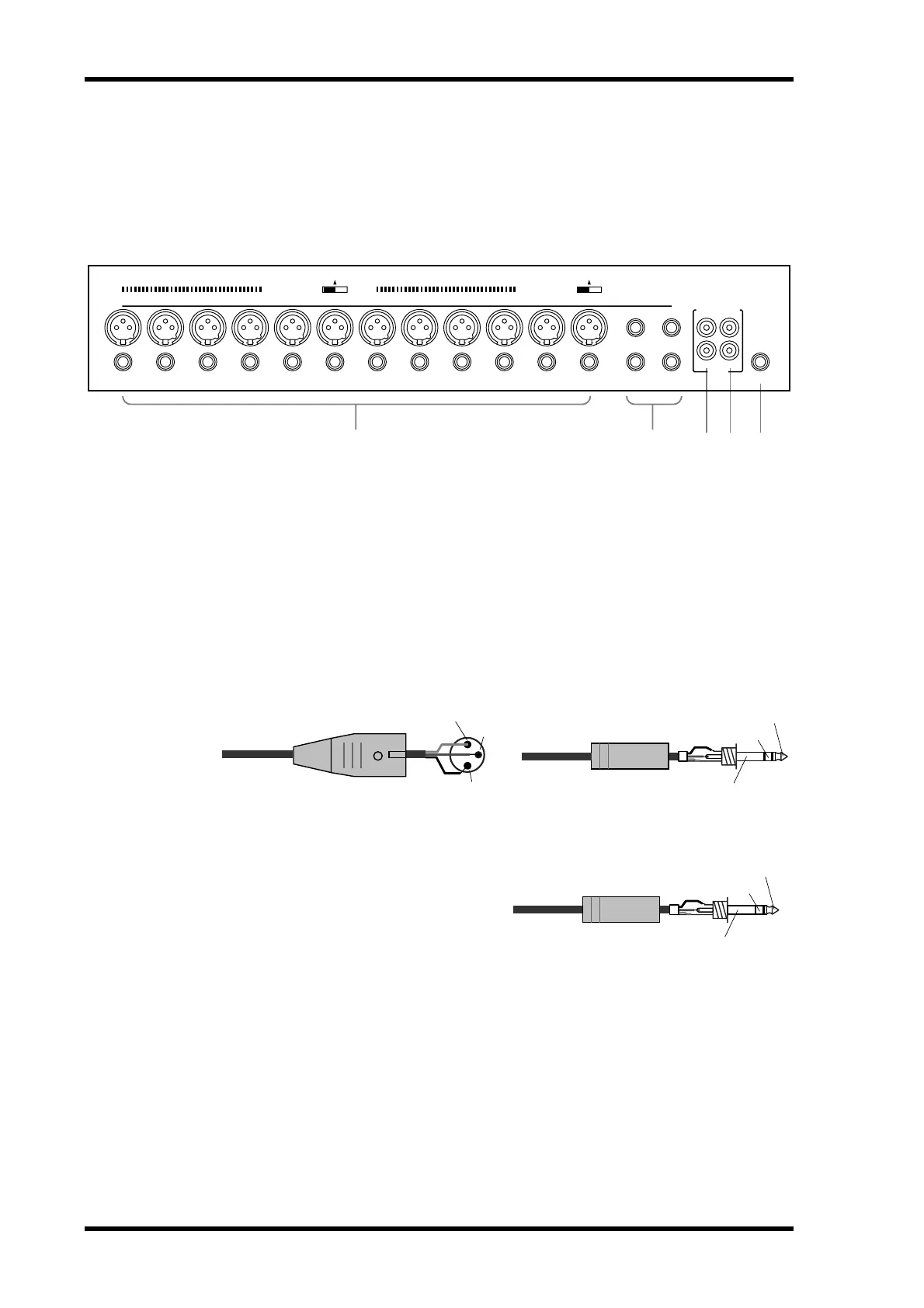
Inputs & Outputs
Input and output connectors are located on the top and rear panels.
Top Panel
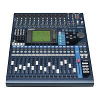
A INPUT (BAL) 1–12
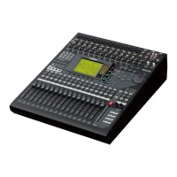
Input channels 1 through 12 feature balanced XLR-3-31-type and balanced phone jack
connectors, both with a nominal input range of –60 dB to +10 dB. Phantom powering
(+48 V) is supplied to the XLR connectors, with master on/off switches for connectors
1 through 6 and 7 through 12. Phone jacks, which can also be used with unbalanced
phone plugs, have priority over the XLR-type connectors, so when a phone plug is
inserted, the XLR-type connector is disconnected. With their high sensitivity and 26 dB
PAD switches, these inputs can handle a wide range of signals, from condenser micro-
phones to “hot” line levels.
B INPUT (BAL) 13–16
Input channels 13 through 16 feature bal-
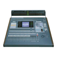
anced phone jack connectors, with a
nominal input range of –20 dB to +10 dB.
These inputs are designed for use with
line-level sources, and can also be used
with unbalanced phone plugs. The stereo
outputs of an external effects processor or
other stereo device can be connected here.
534
1 2
PHANTOM +48V
OFF
ON
PHANTOM +48V
INPUT (BAL)
2TR
PHONES
L
R
IN OUT
13
14
15
16
OFF
ON
–10dBV (UNBAL)
Male XLR plug
1 (ground)
3 (cold)
2 (hot)
1/4" TRS phone plug
Tip (hot)
Ring (cold)
Sleeve (ground)
1/4" TRS phone plug
Tip (hot)
Ring (cold)
Sleeve (ground)