7-16
Power unit assembly
0
1
2
3
4
5
6
7
8
9
10
A
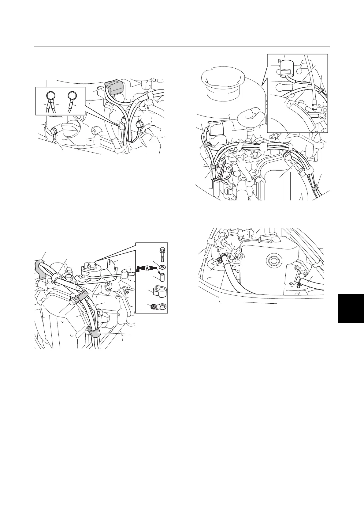
10. Connect the CDI unit coupler b, CDI unit
ground lead c, engine shut-off switch
ground lead d, and ground lead c.
11. Install the engine shut-off switch lead a
and ground lead c to the holders n, o,
and p.
12. Install the bracket q, lever r, throttle
cam s, collar t, washer u, and holder
v.
13. Install the throttle link rod w and cap x.
14. Fasten the engine shut-off switch lead a,
CDI unit ground lead c, CDI unit lead e,
engine shut-off switch ground lead d,
and ground leads c and y using the
plastic ties z.
15. Connect the fuel hoses A and B, and
then fasten them using the clamps C.
16. Connect the throttle cables D, and then
adjust the throttle cables D. See steps
2–9 in “Adjusting the throttle cable and
throttle link” (6-14).
17. Connect the choke cable E, and then
install the holder F. See steps 9 and 10
in “Installing the primer pump” (6-7).
18. Tighten the choke holder bolt G to the
specified torque.
c
c
d
d
c
b
c
c
a
c
p
o
w
q
x
r
s
u
n
v
t