viii
Outboard Rigging Guide - 2001
GENERAL RIGGING INFORMATION
Fuel Line Routing and Installation
Fuel System Check
1. Ensure there is an anti-syphon valve or man-
ual shut-off valve located on the fuel tank
pickup tube.
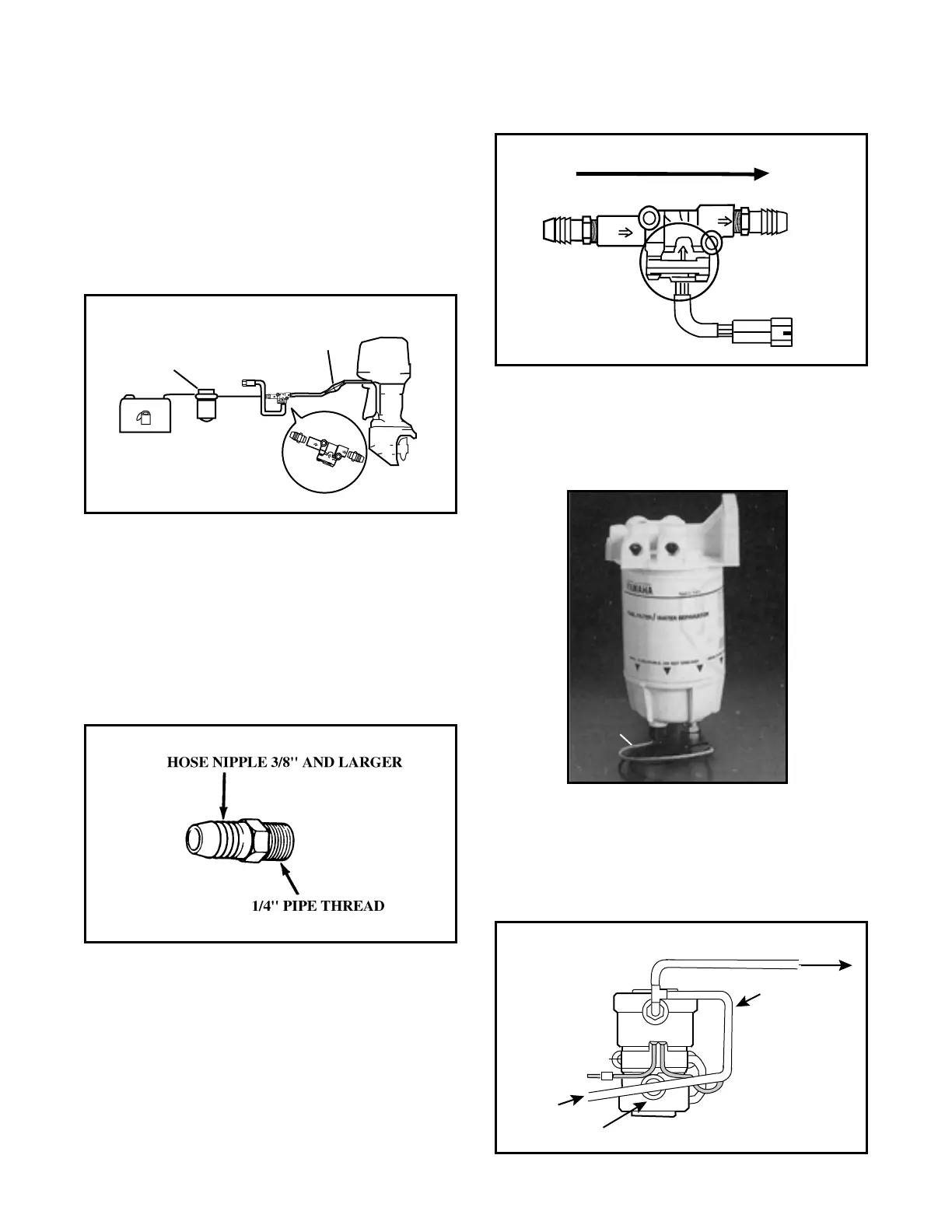
2. Install the fuel line from the fuel tank pickup
to the inlet side of the water fuel separator fil-
ter. Use only GOOD stainless steel clamps.
NOTE: Ensure that all fuel fittings are sealed
with teflon tape or equivalent fuel system sealer.
Only apply sealer to the external threads of the
fuel fitting. Any sealer on the internal bore could
result in fuel system contamination.
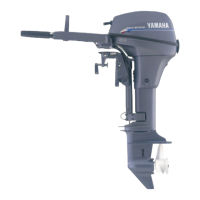
3. OPTIONAL: Run fuel line from the outlet
side of the water fuel separator to the fuel
management sender inlet side. The fuel flow
is indicated by the arrows in the following
illustration. Install the fuel sender with the
side arrow pointing up.
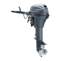
NOTE: An optional feature for the fuel manage-
ment system is a water detection sender for the
water/fuel separator. This provides a visual signal
to the consumer to indicate if water is in the fuel
system.
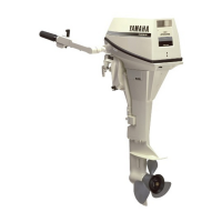
4. The primer bulb or optional electric fuel
primer pump may now be installed.
NOTE: An electrical primer pump must have a
bypass tube installed.