CYLINDER HEAD AND ROCKER ARMS
5-8
REMOVING THE CYLINDER HEAD
1. Remove:
• Flywheel cover
Refer to “FLYWHEEL” on page 5-21.
2. Align:
• Piston
(to top dead center [TDC] on the compres-
sion stroke)
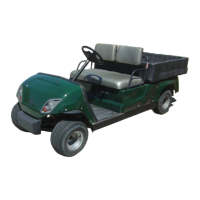
a. Carefully insert a dial indicator into the
spark plug hole until it contacts the top of
the piston.
b. Rotate the flywheel clockwise to position
the piston at top dead center (TDC) on the
compression stroke (when the dial indica-
tor inserted into the spark plug hole reach-
es the highest position).
Check that both rocker arms are loose. If
the rocker arms are not loose, rotate the
flywheel one full turn (360°).
c. Make alignment marks “a” on the flywheel
and crankcase when the piston is at top
dead center (TDC) on the compression
stroke so that the piston can be positioned
at TDC during cylinder head installation.
3. Remove:
• Push rods
• Rocker arm shafts
• Rocker arms
Make a note of the position of each push rod,
rocker arm shaft and rocker arm so that they can
be reinstalled in their original place.
4. Remove:
• Cylinder head bolts
• Loosen the bolts in the proper sequence as
shown.
• Loosen each bolt 1/2 of a turn at a time. After
all of the bolts are fully loosened, remove them.
CHECKING THE CYLINDER HEAD
1. Eliminate:
• Combustion chamber carbon deposits
(with a rounded scraper)
Do not use a sharp instrument; otherwise,
the following may be damaged or scratched:
• Spark plug bore threads
• Valve seats
2. Check:
• Cylinder head
Damage/scratches → Replace.
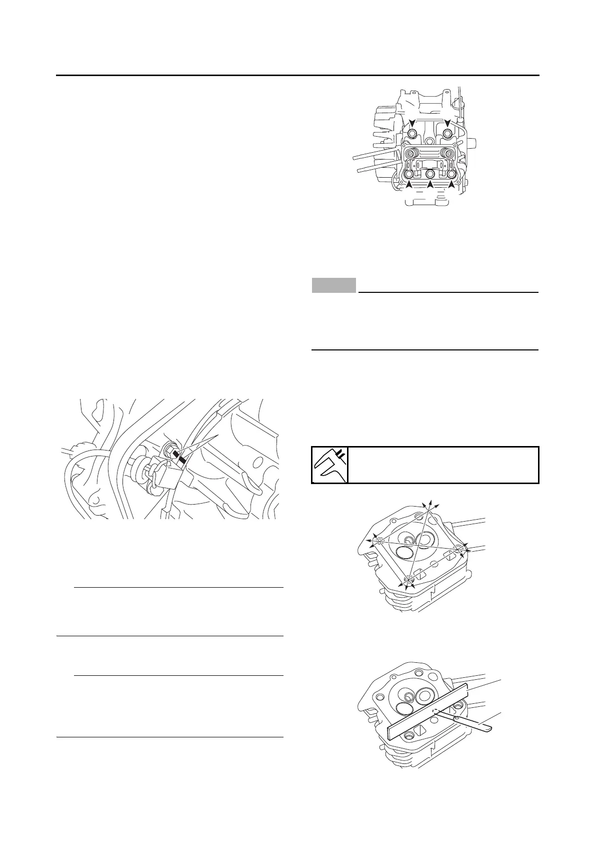
3. Measure:
• Cylinder head warpage
Out of specification → Resurface the cylinder
head.
a. Place a straightedge “1” and a thickness
gauge “2” across the cylinder head.
Warpage limit
0.05 mm (0.002 in)