ELECTRICAL COMPONENTS (YUM1A/YUM2A)
8-56
b. Check the starter generator operation.
CHECKING THE VOLTAGE REGULATOR
1. Remove:
• Drive belt
Refer to “REPLACING THE DRIVE BELT
(YUM1A/YUM2A)” on page 3-8.
2. Check:
• Charging voltage
Out of specification → Replace the voltage
regulator.
a. Connect the engine tachometer to the
spark plug lead.
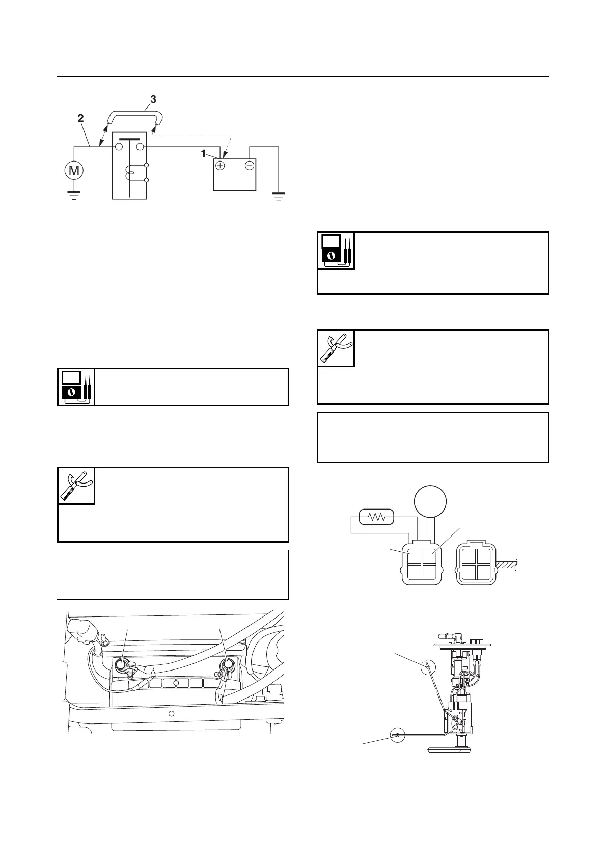
b. Connect the digital circuit tester to the bat-
tery as shown.
c. Start the engine and let it run at approxi-
mately 5000 r/min.
d. Measure the charging voltage.
CHECKING THE FUEL SENDER
1. Disconnect:
• Fuel pump coupler
(from the wire harness)
2. Remove:
• Fuel pump assembly
(from the fuel tank)
3. Check:
• Fuel sender resistance
Out of specification → Replace the fuel pump
assembly.
a. Connect the digital circuit tester to the fuel
sender terminals as shown.
b. Move the fuel sender float to minimum “3”
and maximum “4” level positions.
c. Measure the fuel sender resistance.
Charging voltage
above 14 V at 5000 r/min
Digital circuit tester (CD732)
90890-03243
Model 88 Multimeter with ta-
chometer
YU-A1927
• Positive tester probe →
positive battery terminal “1”
• Negative tester probe →
negative battery terminal “2”
Sender unit resistance (full)
4–10 Ω
Sender unit resistance (empty)
93–100 Ω
Digital circuit tester (CD732)
90890-03243
Model 88 Multimeter with ta-
chometer
YU-A1927
• Positive tester probe →
pink “1”
• Negative tester probe →
black “2”