ELECTRICAL COMPONENTS (YUM1A/YUM2A)
8-53
c. Make sure that the current is higher than
the standard charging current written on
the battery.
If the current is lower than the standard charging
current written on the battery, this type of battery
charger cannot charge the VRLA (Valve Regu-
lated Lead Acid) battery. A variable voltage
charger is recommended.
d. Charge the battery until the battery’s
charging voltage is 15 V.
Set the charging time at 20 hours (maximum).
e. Measure the battery open-circuit voltage
after leaving the battery unused for more
than 30 minutes.
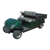
6. Install:
• Battery
7. Connect:
• Battery leads
(to the battery terminals)
First, connect the positive battery lead “1”,
and then the negative battery lead “2”.
8. Check:
• Battery terminals
Dirt → Clean with a wire brush.
Loose connection → Connect properly.
9. Install:
• Under-seat panel
• Seat cushion
Refer to “GENERAL CHASSIS (1)” on page
4-1.
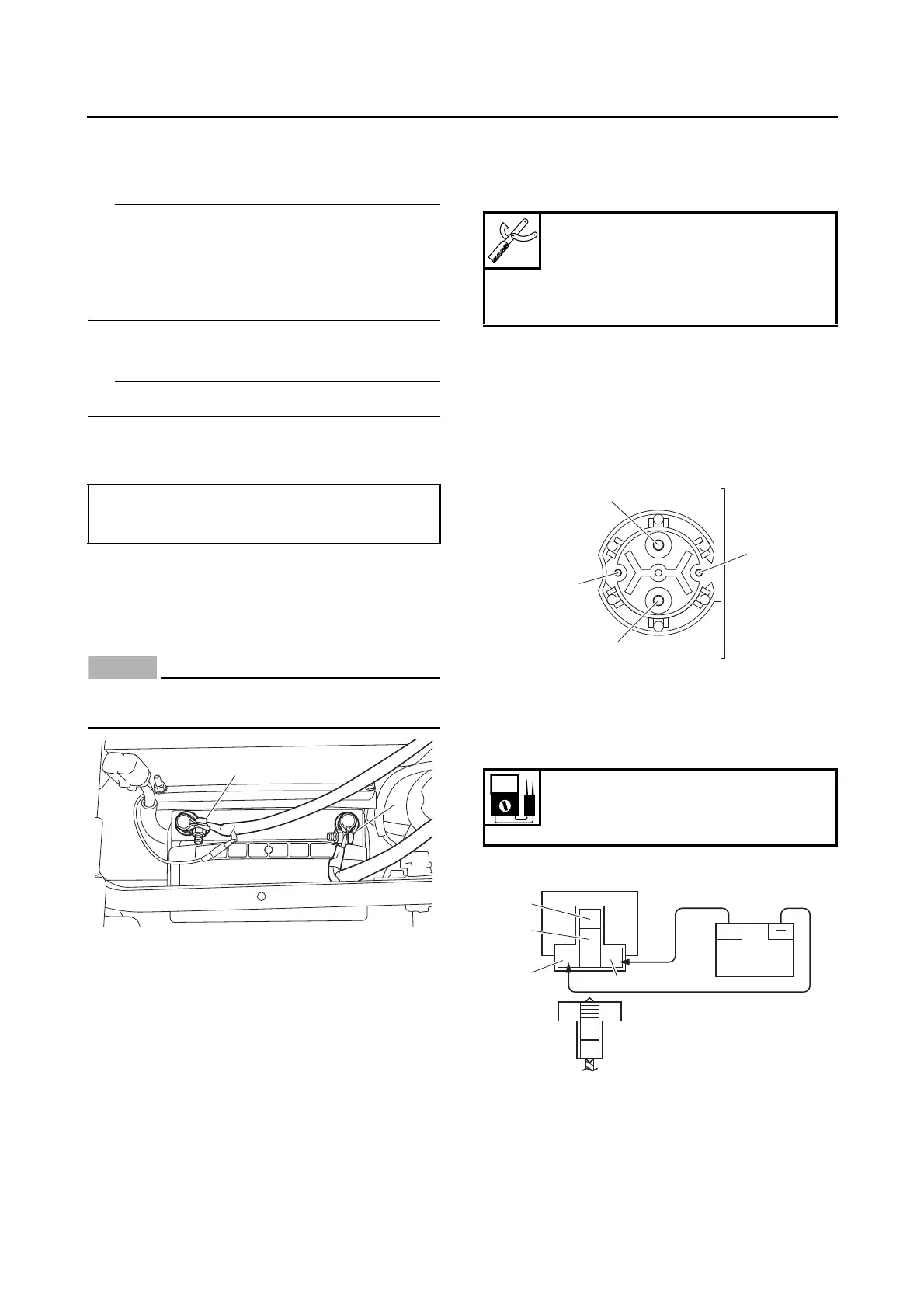
CHECKING THE RELAYS
Check each switch for continuity with the digital
circuit tester. If the continuity reading is incor-
rect, replace the relay.
1. Disconnect the wire harness from the relay.
2. Connect the digital circuit tester and battery
(12 V) to the relay terminal as shown.
Check the relay operation.
Out of specification → Replace.
Main relay
Fuel pump relay
12.8 V or more --- Charging is complete.
12.7 V or less --- Recharging is required.
Under 12.0 V --- Replace the battery.
Digital circuit tester (CD732)
90890-03243
Model 88 Multimeter with ta-
chometer
YU-A1927
1. Positive battery terminal
2. Negative battery terminal
3. Positive tester probe
4. Negative tester probe
Result
Continuity
(between “3” and “4”)
1. Positive battery terminal
2. Negative battery terminal
3. Positive tester probe
4. Negative tester probe